System and method for vehicle navigation and piloting including absolute and relative coordinates

a technology of absolute and relative coordinates and vehicle navigation, applied in the field of digital maps, geographical positioning systems, vehicle navigation, can solve the problems of prone to accumulating small amounts of positional errors, errors still exist, and gps receivers experiencing intermittent or poor signal reception, etc., to achieve enhanced driving directions

Inactive Publication Date: 2008-10-02
TELE ATLAS NORTH AMERICA
View PDF25 Cites 225 Cited by
  • Summary
  • Abstract
  • Description
  • Claims
  • Application Information

AI Technical Summary

Benefits of technology

[0008]Disclosed herein is a navigation system for use in a vehicle. The navigation system includes an absolute position sensor, such as GPS, in addition to one or more additional sensors, such as a camera, laser scanner, or radar. The navigation system further comprises a digital map or database, that includes records for at least some of the vehicle's surrounding objects, including lane markers, street signs, and buildings, in addition to traditional information such as street centerlines, street names and addresses. These records include relative positional attributes in addition to the traditional absolute positions. As the vehicl

Problems solved by technology

This technique is prone to accumulating small amounts of positional error, which can be partially corrected with “map matching” algorithms.
Even though on a global or macro-scale satellite technology is extremely accurate; on a local or micro-scale small positional errors still do exist.
This is primarily because the GPS receiver can experience an intermittent or poor signal reception, and also because both the centerline representation of the streets and the measured position from the GPS receiver may only be accurate to within several meters.
Higher performing systems use a combination of dead-reckoning an

Method used


Image

  • System and method for vehicle navigation and piloting including absolute and relative coordinates
  • System and method for vehicle navigation and piloting including absolute and relative coordinates
  • System and method for vehicle navigation and piloting including absolute and relative coordinates

Examples


example 1

Vehicles within Direct Sensor Range of Each Other

[0052]In this example, the sensor within each vehicle can identify the other vehicle, and can estimate its distance and bearing. The navigation or collision avoidance system can judge if it is closing in such a way that there is a possibility of collision. In this example the digital map is not really needed although a digital map is useful to give some context to the situation (for example a bend in the road might help to explain why two vehicles are on an apparent collision path, but that it should be anticipated that the vehicles will soon turn away from one another). In this direct sensor case the vehicle sensors themselves use relative measurements to make these observations. This case also applies to the sensing of stationary objects. Again, no digital map is needed to sense a stationary object, but it is helpful to map match to the objects in a map to both identify the objects in relationship to the road geometry, and also to o...

example 2

Vehicles within Sensor Range of the Same Object

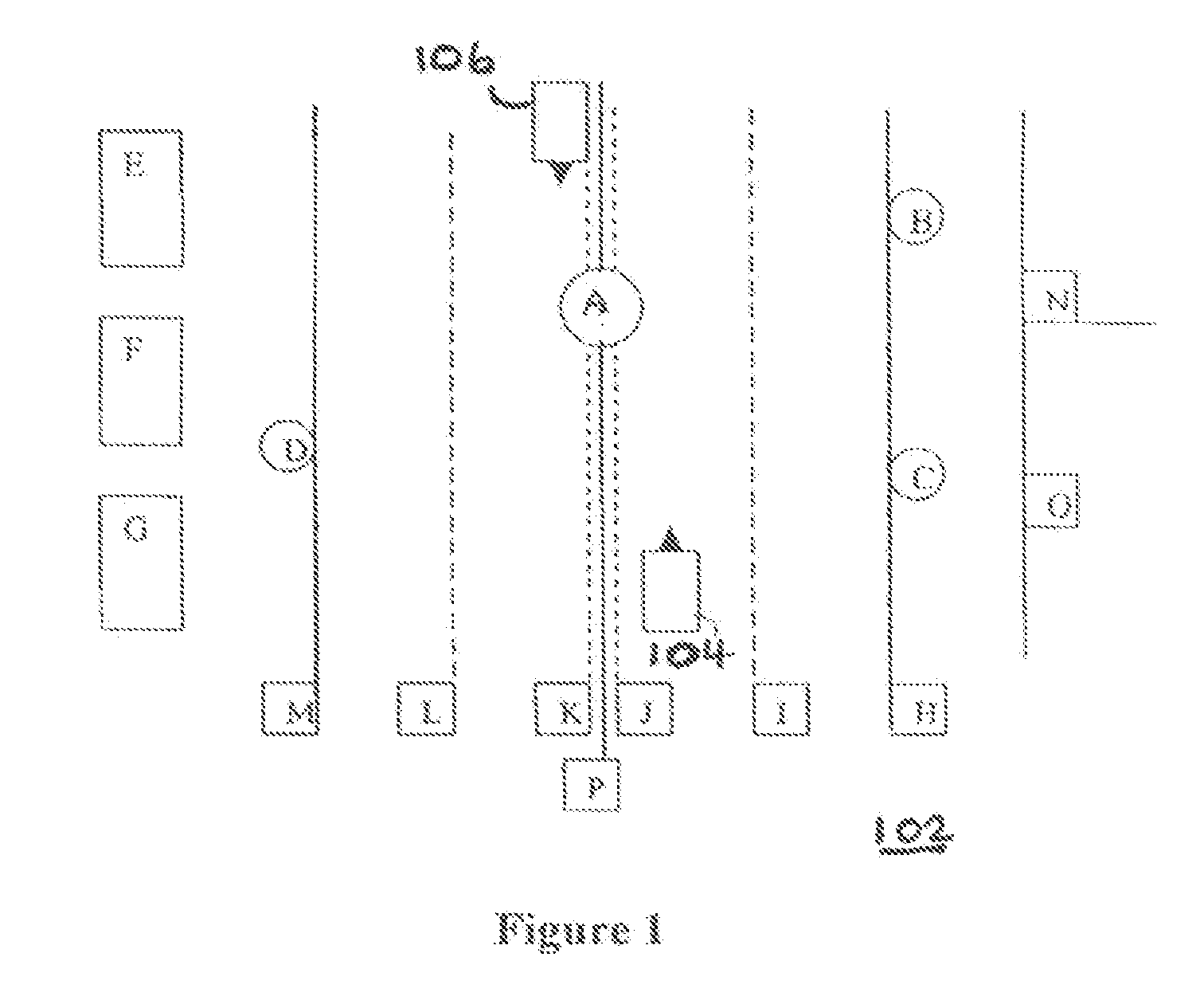
[0054]In this example, the sensors on board each vehicle may not have a sufficient range or sensitivity to detect the other vehicle directly. Perhaps there are obstructions such as a hill blocking direct sensor detection. However each sensor in a vehicle can detect a common object, such as the sign A in FIG. 1. As in the example described above, each vehicle can use “object-based map matching” to match to the sign A using the nominal accuracies of today's absolute position determinations both on board the vehicle and within the map. Unlike the typical “map matching” feature mentioned above as part of today's navigation systems, which matches the estimated position of the vehicle against road centerlines contained in the map; in accordance with an embodiment of the invention, object-based map matching matches the estimated position and characteristics of physical objects sensed by the vehicle against one or more physical objects and thei...

example 3

Vehicles Beyond the Sensor Range of the Same Object

[0057]In the most general case, the sensors on board the two vehicles may not be able to detect the other vehicle, or a common object, but may still be able to detect objects in their immediate vicinity. For example, there may be no convenient object such as the sign A in FIG. 1 that happens to be between the two vehicles and visible to both vehicles. Instead, vehicle 104 may only be able to detect signs B and C; and vehicle 106 may only be able to detect sign D. Even so, vehicle 104 can obtain a very accurate relative position and heading based on its relative sensor measurements from objects B and C. Similarly, vehicle 106 can obtain a very accurate relative position and heading from its measurements of object D and its heading estimate. Because B and C and D all have accurate relative positions to each other as stored in the map databases, these accurate relative positions can then be used by the vehicles for improve driving, rou...


PUM


Abstract

A navigation system for use in a vehicle. The system includes an absolute position sensor, such as GPS, in addition to one or more additional sensors, such as a camera, laser scanner, or radar. The system further comprises a digital map or database that includes records for at least some of the vehicle's surrounding objects. These records can include relative positional attributes and traditional absolute positions. As the vehicle moves, sensors sense the presence of at least some of these objects, and measure the vehicle's relative position to those objects. This information, together with the absolute positional information and the added map information, is used to determine the vehicle's location, and support features such as enhanced driving directions, collision avoidance, or automatic assisted driving. In accordance with an embodiment, the system also allows some objects to be attributed using relative positioning, without recourse to storing absolute position information.

Description

CLAIM OF PRIORITY[0001]This application claims the benefit of U.S. Provisional Patent Application titled “SYSTEM AND METHOD FOR VEHICLE NAVIGATION AND PILOTING INCLUDING ABSOLUTE AND RELATIVE COORDINATES”; Application No. 60 / 891,019; inventor Walter B. Zavoli; filed Feb. 21, 2007, and herein incorporated by reference.COPYRIGHT NOTICE[0002]A portion of the disclosure of this patent document contains material which is subject to copyright protection. The copyright owner has no objection to the facsimile reproduction by anyone of the patent document or the patent disclosure, as it appears in the Patent and Trademark Office patent file or records, but otherwise reserves all copyright rights whatsoever.FIELD OF THE INVENTION[0003]The invention relates generally to digital maps, geographical positioning systems, and vehicle navigation, and particularly to a system and method for vehicle navigation and piloting using absolute and relative coordinates.BACKGROUND[0004]Within the past several...

Claims


Application Information

Patent Timeline
IPC IPC(8): G01C21/26G01C21/00
CPCG01C21/28G01C21/30
Inventor ZAVOLI, WALTER B.
Owner TELE ATLAS NORTH AMERICA
Why Eureka
Try Eureka