
Method For Packing Solar Battery Elements and Package For Solar Battery Elements

a technology of solar cells and solar energy, applied in the field of solar cell elements and packaging, can solve the problems of high cost of processing the holding trenches, high cost of transportation, and high cost of packaging work, and achieve the effects of preventing cracking and chipping, sufficient strength, and convenient packing

Inactive Publication Date: 2008-10-16
KYOCERA CORP
View PDF7 Cites 32 Cited by
  • Summary
  • Abstract
  • Description
  • Claims
  • Application Information

AI Technical Summary

Benefits of technology

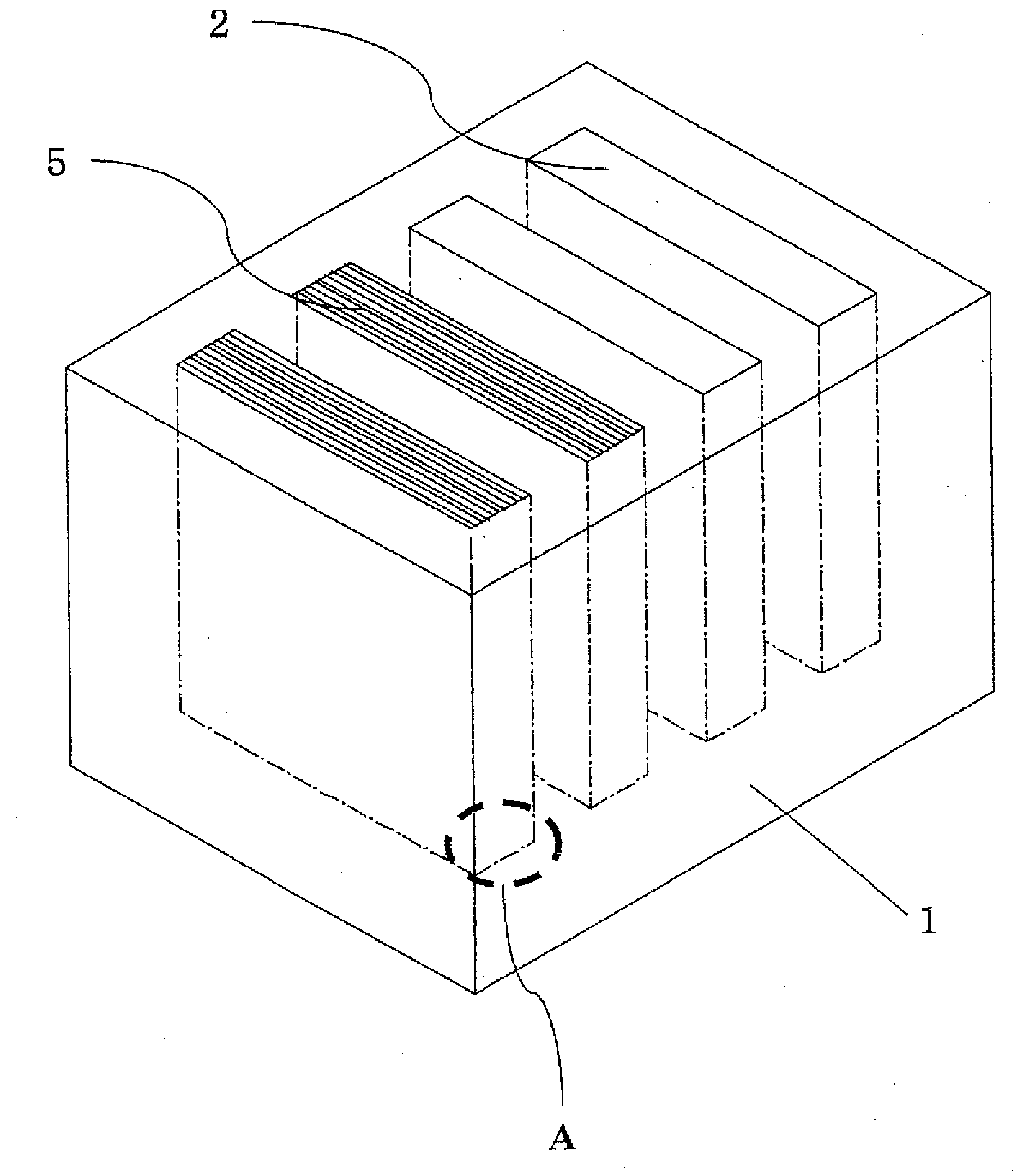
[0008]The present invention is provided in view of these problems with the prior art, and an object thereof is to provide a method for packing solar battery elements and a package where cracking and chipping can be prevented from occurring during the packing work and transportation, and the solar battery elements can be easily packed.
[0024]In addition, a side of the layers of the assembly of solar battery elements is located on the bottom surface side of the above described opening, and thus, the weight of the solar battery elements can be dispersed instead of being collected to a certain solar battery element at the time of packing.

Problems solved by technology

In the conventional structure, however, it is necessary to set the solar battery elements 103 in the trenches of the buffering bodies 101 one by one, and therefore, the packing work is extremely troublesome.
As a result, it becomes necessary to increase the precision in the width of the holding trenches 102, and consequently, problems arise such that the cost for processing the holding trenches 102 becomes high and the cost for transportation greatly increases, particularly when the buffering bodies 101 are disposed of at the shipping destination without being reused.

Method used


Image

  • Method For Packing Solar Battery Elements and Package For Solar Battery Elements
  • Method For Packing Solar Battery Elements and Package For Solar Battery Elements
  • Method For Packing Solar Battery Elements and Package For Solar Battery Elements

Examples


Embodiment Construction

[0065]In the following, the method for packing solar battery elements according to the present invention is described. In the present document, an opening 2 indicates the entirety of a recess formed in a container 1.

[0066]First, solar battery elements, which are articles to be packed according to the present invention, are described.

[0067]FIG. 13 is a schematic diagram showing the structure of a solar battery element in the present invention. 21 indicates a semiconductor substrate, 22 indicates a diffusion layer, 23 indicates a reflection preventing film, 24 indicates a front surface electrode, 25 indicates a rear surface electrode, 25a indicates rear surface busbar electrodes, 25b indicates a rear surface electricity collecting electrode and 26 indicates a rear surface electrical field region.

[0068]A semiconductor substrate 21 of a p type semiconductor made of single crystal silicon or polycrystal silicon having a thickness of approximately 0.2 mm to 0.5 mm and dimensions of approx...


PUM

PropertyMeasurementUnit
Heataaaaaaaaaa

Abstract

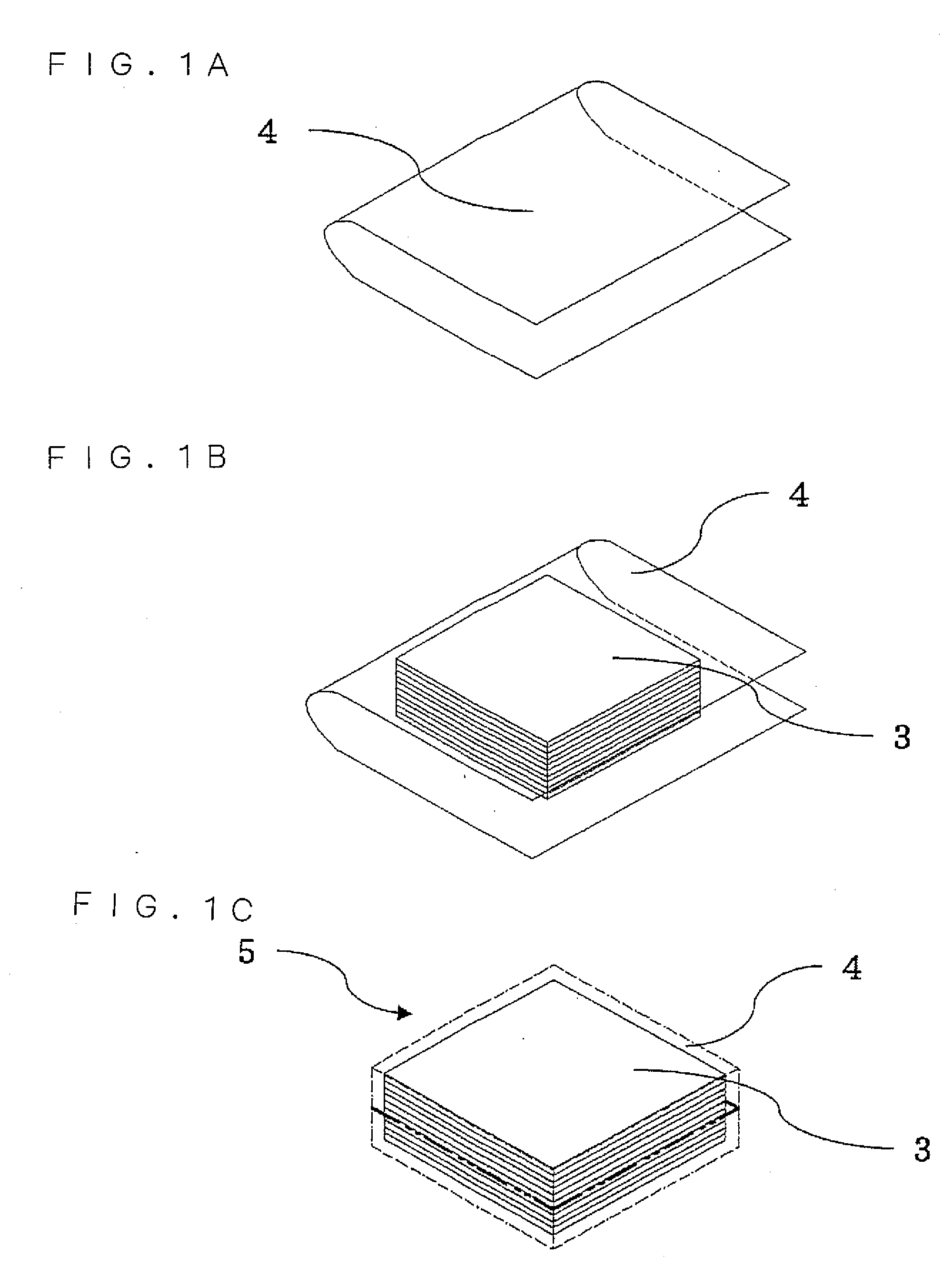
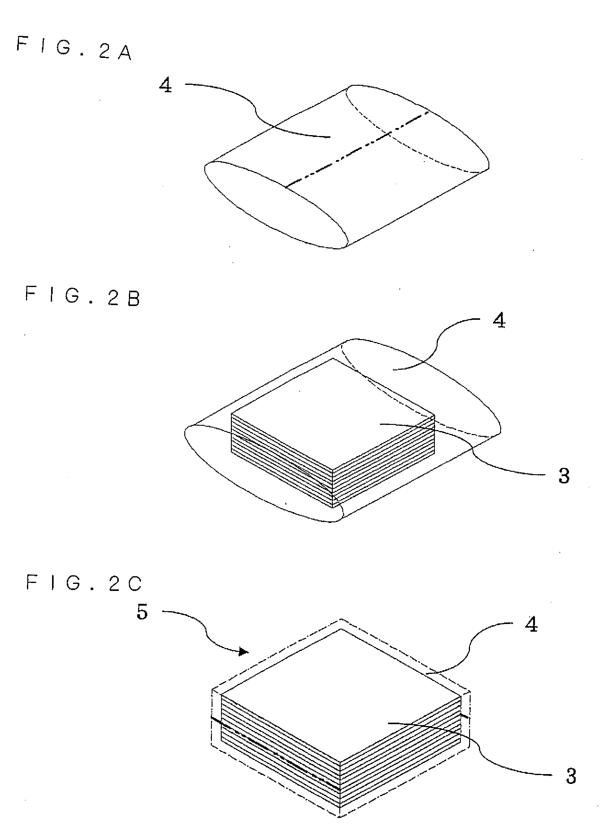
An object of the invention is to provide a method for packing solar battery elements where cracking or chipping does not occur during the packing work and transportation, and the solar battery elements can be easily packed. In addition, in order to achieve the above described object, the method includes: a first packing step of covering a plurality of layered solar battery elements (3) with a heat-shrinkable film (4); a first heating step of heating this heat-shrinkable film (4) so that the solar battery elements 3 are held as an assembly (5); and a second packing step of inserting the assembly (5) into an opening (2) of a container (1) having the opening (2) for holding this assembly (5).

Description

TECHNICAL FIELD[0001]The present invention relates to a method for packing solar battery elements, and in particular, to a packing method and a package which allow solar battery elements to be transported safely by reducing the damage to the solar battery elements.BACKGROUND TECHNOLOGY[0002]Solar batteries convert incident light energy to electrical energy. Solar batteries are mainly classified as crystal based solar batteries, amorphous based solar batteries, compound based solar batteries and the like, depending on the type of material used. From among these, most of those circulated in markets at present are crystal based silicon solar batteries, and solar battery elements fabricated from a single crystal or a polycrystal silicon substrate are provided in a thin substrate having a thickness of approximately 200 μm to 300 μm or less, and therefore, feeble against impact and vibration, and thus, cracking and chipping easily occur when solar battery elements are transported.[0003]FI...

Claims


Application Information

Patent Timeline
IPC IPC(8): H01L31/042
CPCB65D75/002B65D85/38H01L31/048H01L21/67369Y02E10/50H01L21/67363
Inventor TANAKA, KUMEHARUSHIMIZU, KOUSEISAKAMOTO, RYUICHI
Owner KYOCERA CORP
Learn More