Organic EL Display Device

a display device and organic technology, applied in static indicating devices, electroluminescent light sources, instruments, etc., can solve the problems of reducing detection accuracy, affecting the design of the structure, and substantially impossible to design the structure, so as to achieve high light emitting efficiency, high light receiving efficiency, and efficient manufacture of the organic el display device

Inactive Publication Date: 2008-10-16
PANASONIC LIQUID CRYSTAL DISPLAY CO LTD +1
View PDF1 Cites 93 Cited by
  • Summary
  • Abstract
  • Description
  • Claims
  • Application Information

AI Technical Summary

Benefits of technology

[0020]By adopting either one of the third means and the fourth means, it is possible to provide an organic EL display device which exhibits both of high light emitting efficiency and high light receiving efficiency.
[0021]Not only by simply making the layered structure of the light emitting element and the layered structure of the light receiving element different from each other but also by using a portion of the organ...

Problems solved by technology

When the power source line is used as a detection path for detecting the electromotive force as described above, a load capacitance is increased thus lowering the detection accuracy.
Although the patent document 1 also discloses the structure in which the power source line also functi...

Method used


Image

  • Organic EL Display Device
  • Organic EL Display Device
  • Organic EL Display Device

Examples


embodiment 1

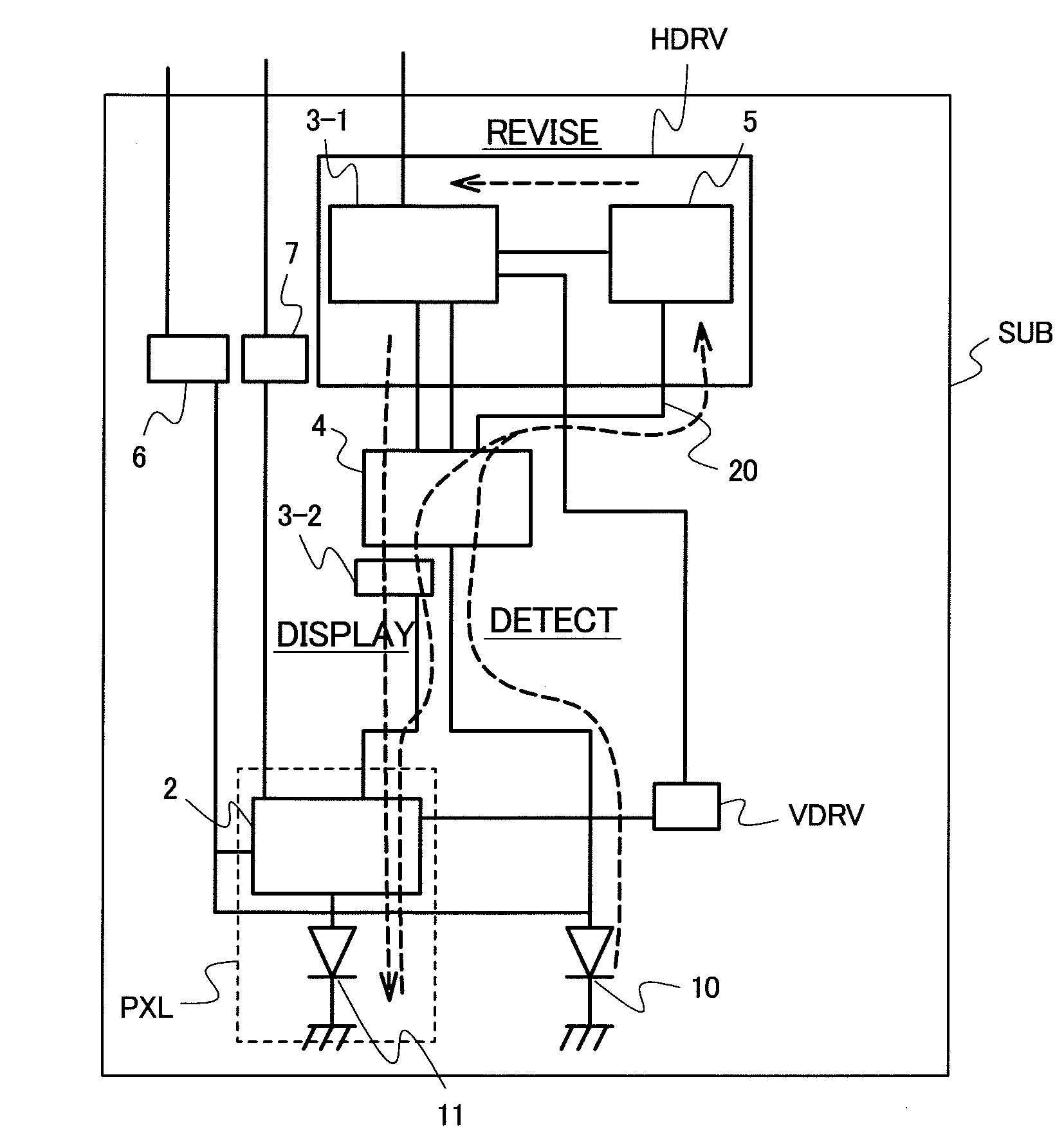
[0059]FIG. 4 shows the basic constitution of a display panel of the embodiment 1. The display panel of the embodiment 1 includes a pixel circuit 2, a display control part 3-1, a color selection circuit 3-2, a detection switch 4, the detection circuit 5, a detection-use power source 6, a display-use power source 7, a reference element 10, a display element 11, and the scanning line drive circuit VDRV.

[0060]The display control part 3-1, the detection circuit 5 and the detection-use power source 6 are incorporated in the signal line drive circuit HDRV shown in FIG. 22.

[0061]A first terminal of the signal line drive circuit HDRV is directly connected to the detection switch 4, and a second terminal which differs from the first terminal is connected to the detection switch 4 via the detection circuit 5.

[0062]The pixel circuit 2 is, as described above, connected to the signal line DATA, the scanning line SCAN, the power source line POWER, and the detection control line DET. The signal lin...

embodiment 2

[0098]FIG. 12 shows one constitutional example relating to the reference element, the detection line and the display element. In this constitution, one current source is used, a plurality of reference elements is used, and the reference elements and the display elements are compared with each other. Further, this embodiment also provides the constitution which detects the plurality of elements collectively. Assuming the number of elements to be detected simultaneously as n pieces, n pieces of reference pixels are prepared and a current supply quantity of the current source is increased n times with respect to one-piece detection.

[0099]A reference line 60 is connected to a holding part 23 for holding a reference voltage. A detection-use current source 12 used in common is connected to the detection line 20 and, further, the display element 50 (corresponding to the display element 11 shown in FIG. 4), the display element 51 (corresponding to the display element 11 shown in FIG. 4), th...

embodiment 3

[0102]FIG. 13 shows one constitutional example relating to the reference element, the detection line and the display element. In this constitution, a reference element is used in addition to the display elements, and the detection voltage of the reference element and the detection voltages of the display elements are compared with each other. A reference element 55 (corresponding to the reference element 10 shown in FIG. 4) and a detection-use current source 44 (corresponding to the detection-use current source 6 shown in FIG. 6) are connected to the reference line 20. Although only one kind of reference pixel is connected to the reference line 60 in this constitutional example, a plurality of reference elements may preferably be selectively connected to the reference line using a switch. The display element 50 (corresponding to the display element 11 shown in FIG. 4), the display element 51 (corresponding to the display element 11 shown in FIG. 4), the display element 52 (correspon...


PUM


Abstract

The present invention provides an organic EL display device with high detection accuracy which can enhance both of light emission efficiency and light reception efficiency. In an organic EL display device which includes organic thin film elements, a power source line is connected to the organic thin film elements via drive TFTs, a signal line is connected to a gate of the drive TFT to supply a potential corresponding to a gray scale signal, a switch is provided for connecting the signal line and the organic thin film element, and the switch is controlled to allow an electric current which is obtained by photoelectric conversion with the organic thin film element to flow in the signal line and the organic thin film element during a period in which a gray scale signal is not applied to the signal line.

Description

CROSS-REFERENCE TO RELATED APPLICATIONS[0001]The disclosure of Japanese Patent Application No. 2007-068695 filed on 2007 / Mar. / 16 (yyyy / mm / dd) including the claims, the specification, the drawings and the abstract is incorporated herein by reference in its entirety.BACKGROUND OF THE INVENTION[0002]1. Field of the Invention[0003]The present invention relates to an organic EL display device including light receiving elements, and more particularly to an organic EL display device in which a light receiving element is constituted of an organic thin film element.[0004]2. Description of the Related Art[0005]Patent document 1 (JP-A-11-75115) discloses a conventional technique relating to an organic EL display device in which a light receiving element is constituted of an organic thin film element.[0006]The patent document 1 discloses the structure in which first organic thin film elements are vertically arranged parallel to each other in the planar direction, a second organic thin film elem...

Claims


Application Information

Patent Timeline
IPC IPC(8): G09G3/30H05B44/00
CPCG09G3/3225G09G3/3283G09G3/3291G09G2300/043G09G2320/029G09G2320/0295G09G2360/148
Inventor TOYODA, HIRONORIKASAI, NARUHIKOMURAKAMI, HAJIME
Owner PANASONIC LIQUID CRYSTAL DISPLAY CO LTD
Why Eureka
Try Eureka