

Compound and organic light-emitting element
a light-emitting element and compound technology, applied in the field of compound and light-emitting element, can solve the problems of light-emitting element, lack of durability, performance change, etc., and achieve the effects of long-lived light emission, high purity, and high luminant
- Summary
- Abstract
- Description
- Claims
- Application Information
AI Technical Summary
Benefits of technology
Problems solved by technology
Method used
Image

Examples
example 1
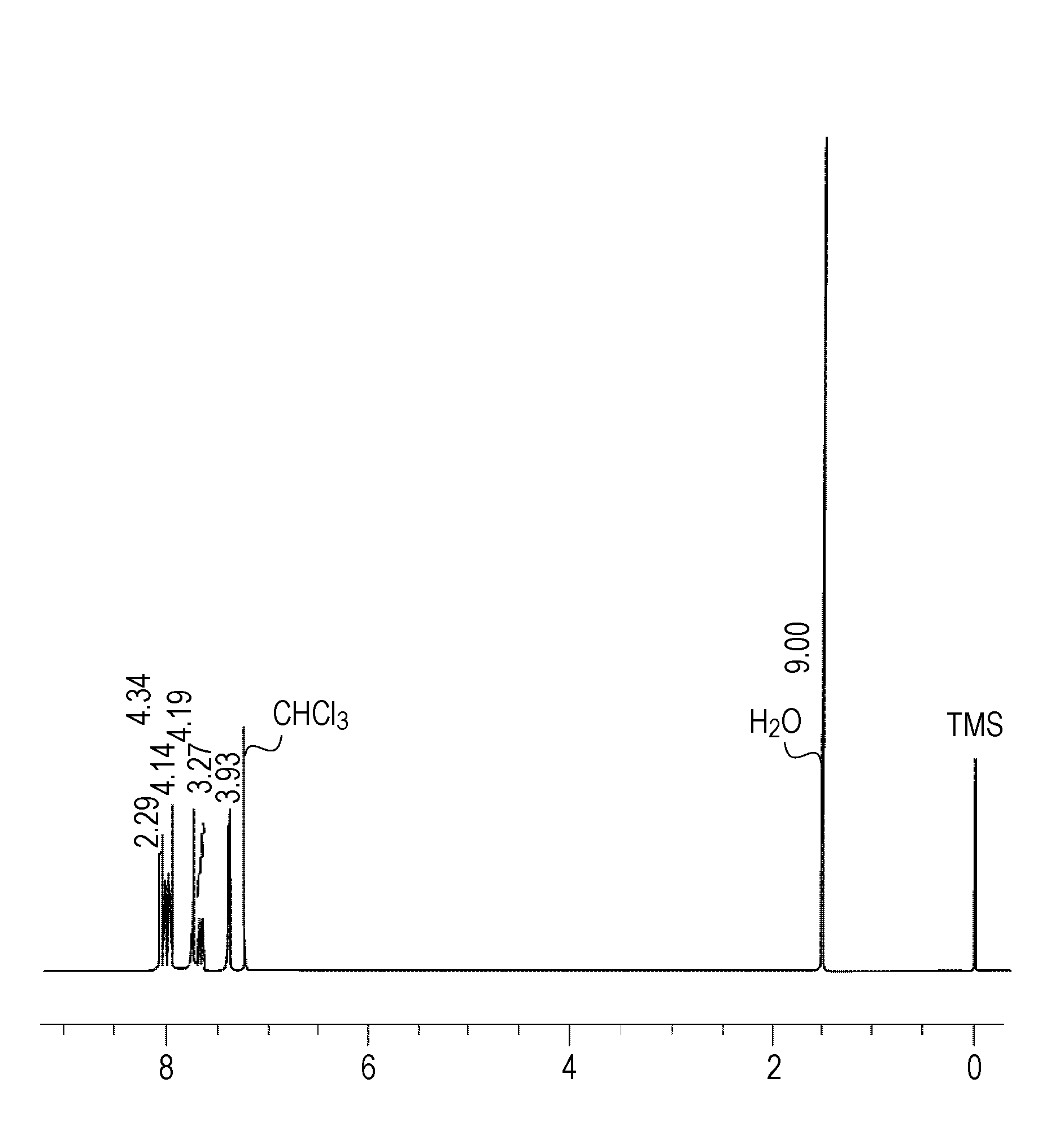
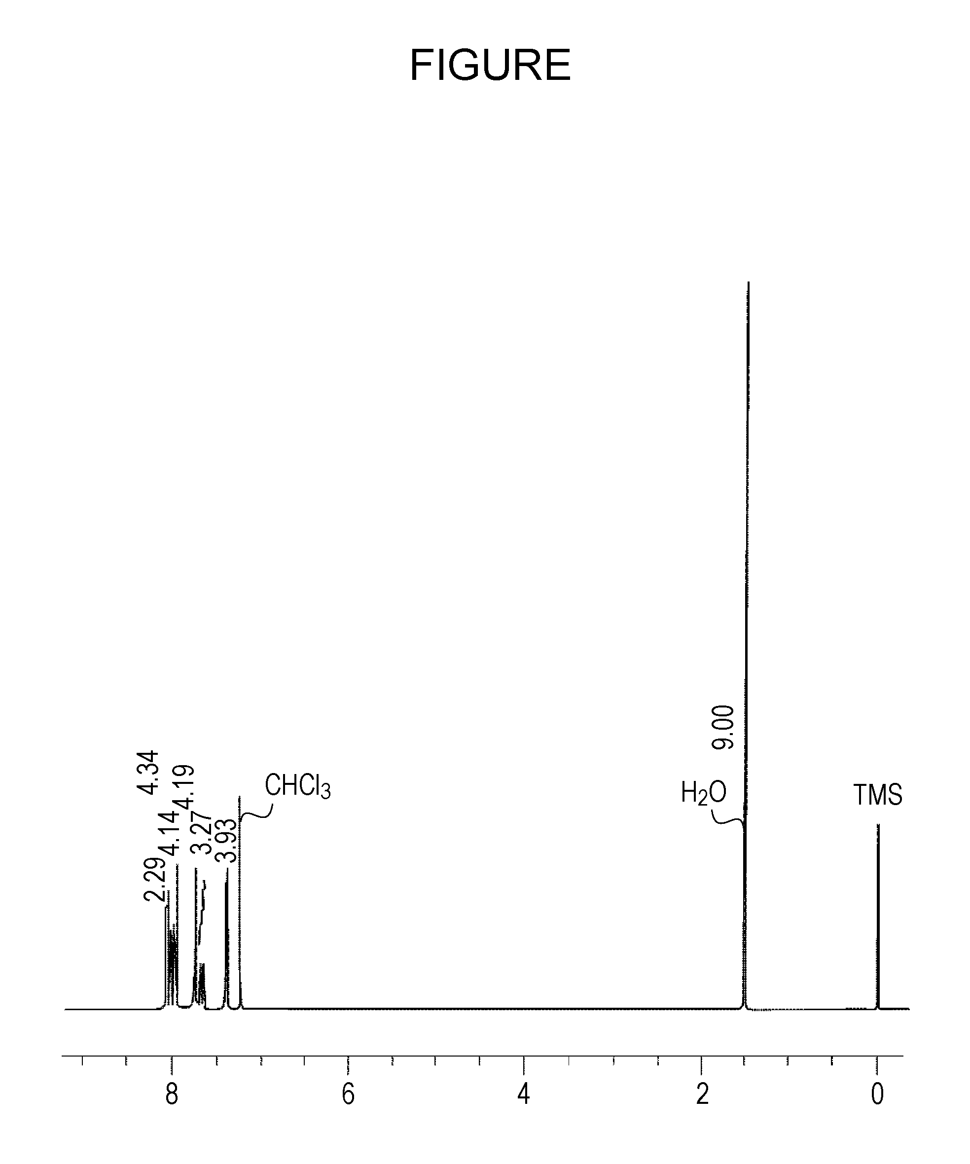
Method for Manufacturing Exemplified Compound No. A-2
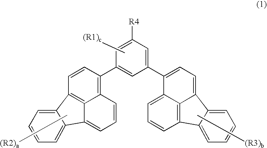
[0072]The exemplified compound A-2 of the present invention can be manufactured, for example, by the following method.
[0073]With reference to J. Am. Chem. Soc. (1991), 113, 4238, which is incorporated herein by reference, 3,5-dibromo-tert-butylbenzene was synthesized from 4-tert-butylaniline.
[0074]In a nitrogen atmosphere, 560 ml (1.93 mmole) of 1,3-dibromo-5-tert-butylbenzene, 1 g (4.06 mmole) of 2-(fluoranthene-3-yl)-4,4,5,5-tetramethyl-[1,3,2]dioxabororane were dissolved in a mixed solvent of toluene (100 ml) and ethanol (50 ml), and an aqueous solution containing 860 mg (8.12 mmole) of sodium carbonate and 15 ml of distilled water was added to the above mixture, followed by stirring at 50° C. for 30 minutes. Subsequently, tetraxis(triphenylphosphine)palladium (446 mg, 0.386 mmole) was added and the resulting mixture was then heated and stirred for 3 hours using a silicone oil bath heated to 90° C. After cooling the mixture to ...
example 2
[0087]An organic light-emitting element was formed by the following method.
[0088]On a glass substrate used as a substrate, a film of indium tin oxide (ITO) having a thickness of 120 nm was formed as an anode by sputtering, so that a transparent conductive support substrate was prepared. The substrate thus formed was washed by ultrasonic waves sequentially using acetone and isopropyl alcohol (IPA) and was then washed by boiling IPA, followed by drying. Furthermore, after UV / ozone washing was performed, the transparent conductive support substrate was used.
[0089]As a hole transport material, a chloroform solution containing compound 1 having the following structure at a concentration of 0.2 percent by weight was prepared.
[0090]The solution thus prepared was dripped onto the ITO electrode, spin coating was performed by rotation thereof at 500 rpm for 10 seconds and then at 1,000 rpm for 1 minute, so that a film was formed. Subsequently, drying was performed at 80° C. for 10 minutes in ...
example 3
[0097]An element was formed in a manner similar to that of Example 2 except that the above exemplified compound No. A-2 as a first compound and compound 3 as a second compound were co-deposited at a ratio of 25:75.
[0098]When a voltage of 4V was applied to the element of this example, light emission having a light emission efficiency of 3.8 μm / W was observed. In addition, the CIE chromaticity was x=0.16 and y=0.22, and hence a blue light emission was observed.
[0099]Furthermore, when a voltage was applied to this element for 100 hours, continuous light emission was stably observed.
PUM
| Property | Measurement | Unit |
|---|---|---|
| temperature | aaaaa | aaaaa |
| Tg | aaaaa | aaaaa |
| LUMO energy | aaaaa | aaaaa |
Abstract
Description
Claims
Application Information