Fluorescent light emitting element and projector

a technology of fluorescent light and projector, which is applied in the direction of lighting and heating equipment, instruments, optics, etc., can solve the problems of increasing phosphor, increasing phosphor, and increasing the heat resistance of the phosphor layer, so as to maximize light emission efficiency, improve the brightness of the fluorescent light emitting element, and achieve high output

Active Publication Date: 2015-07-23
SEIKO EPSON CORP
View PDF15 Cites 21 Cited by
  • Summary
  • Abstract
  • Description
  • Claims
  • Application Information

AI Technical Summary

Benefits of technology

[0030]According to the projector, it is possible to improve brightness of a fluorescent light emitting element compared to a fluorescent light emitting element in the related art by means of using a fluorescent light emitting element capable of obtaining high output by maximizing light emitting efficiency as an illuminating device. Therefore, it is possible to improve brightness (luminance) of a projected image.

Problems solved by technology

However, in the light source device disclosed in JP-A-2011-53320, since the binder as a base material is a resin such as silicone, the heat resistance of the phosphor layer becomes large.
For this reason, there is a problem in that the temperature of the phosphor is increased in response to an increase in the light amount of the excitation light which is incident on the phosphor layer and the increased temperature causes temperature quenching of the phosphor.
Further, in a case where the thickness of the phosphor layer is made extremely thin for a purpose of lowering the heat resistance of the phosphor layer, there is a problem in that excitation light absorptivity (absorbed amount of excitation light) of the phosphor layer is insufficient, fluorescence conversion efficiency of the excitation light is not improved, and thus, an improvement in output of the light source device may not be expected.
However, as described above, there is a problem in that the fluorescence quantum efficiency is decreased when the concentration of the fluorescent substance is increased and sufficient light emitting efficiency may not be obtained.
However, an optimal combination of the concentration of a fluorescent substance and the thickness of a phosphor layer, which can obtain sufficiently high light emitting efficiency, has not been disclosed.

Method used


Image

  • Fluorescent light emitting element and projector
  • Fluorescent light emitting element and projector
  • Fluorescent light emitting element and projector

Examples


first embodiment

[0042

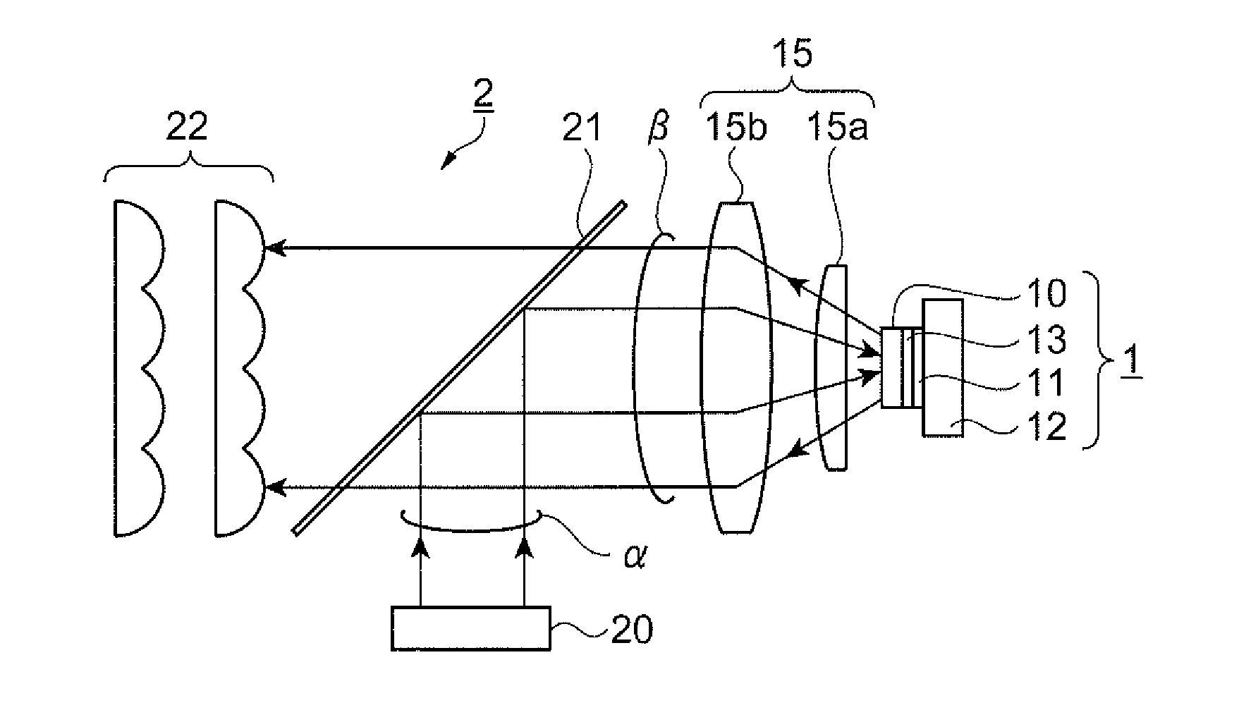
[0043]FIG. 1 is a view schematically illustrating an illuminating device 2 using a fluorescent light emitting element 1 according to a first embodiment. The configuration of the illuminating device 2 (fluorescent light emitting element 1) will be described with reference to FIG. 1.

[0044]Further, for convenience of the description, in order for the size of each member to be made recognizable, dimensions are differentiated from the actual dimensions and each member is appropriately enlarged or reduced for illustration in the following drawings including FIG. 1.

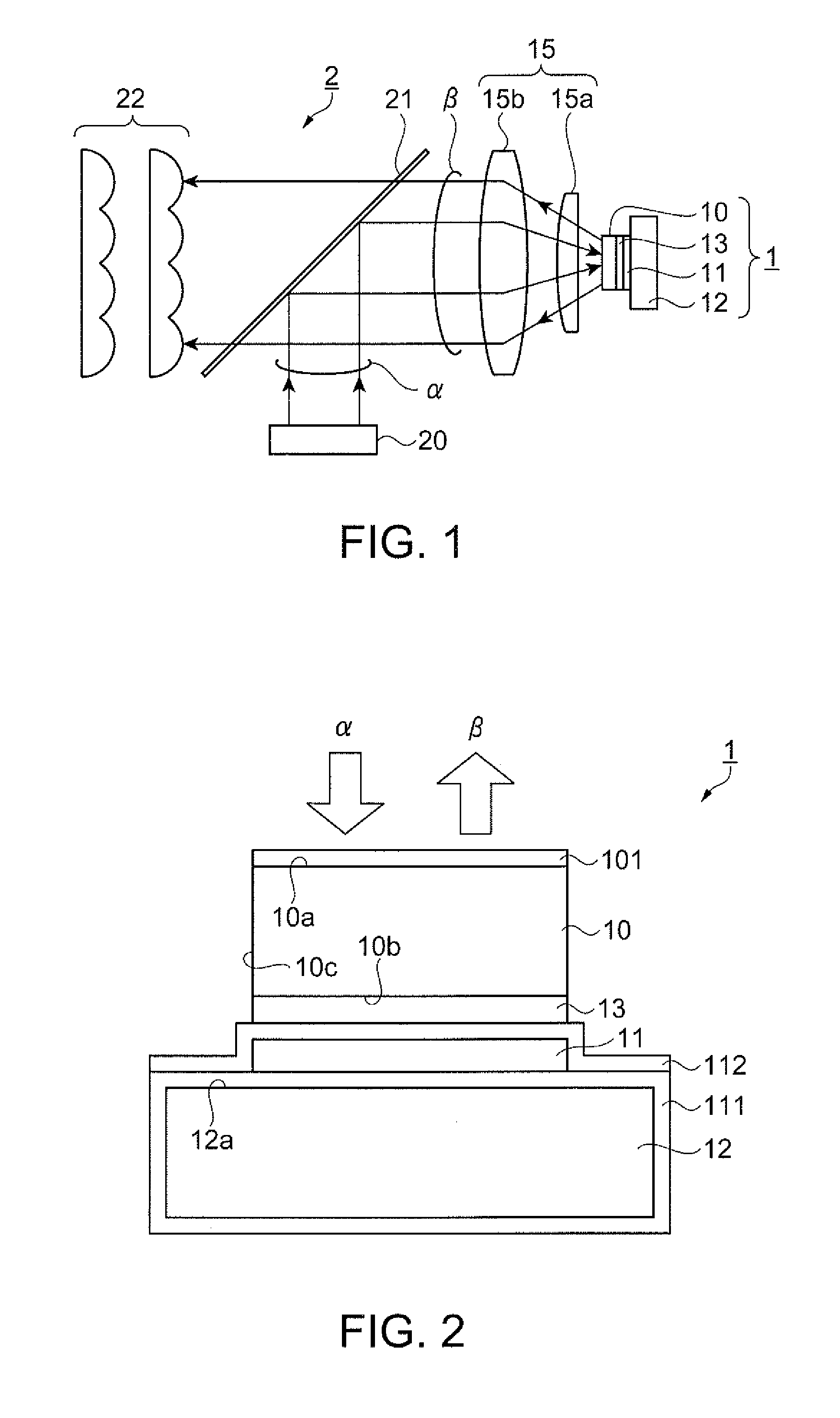
[0045]As illustrated in FIG. 1, the fluorescent light emitting element 1 includes a phosphor layer 10, a reflective film 11 constituting a reflection unit, a substrate 12, and an adhesive layer 13. Further, the illuminating device 2 includes a collimate optical system 15, an excitation light source 20, a dichroic mirror 21, and a lens array 22 in addition to the fluorescent light emitting element 1.

[0046]The phosphor layer ...

second embodiment

[0099

[0100]FIGS. 6A and 6B are views illustrating a configuration of a fluorescent light emitting element 1A according to a second embodiment. FIG. 6A is a plan view illustrating the fluorescent light emitting element 1A and FIG. 6B is a cross-sectional view illustrating the fluorescent light emitting element 1A. The configuration and an operation of the fluorescent light emitting element 1A will be described with reference to FIGS. 6A and 6B.

[0101]As illustrated in FIGS. 6A and 6B, the fluorescent light emitting element 1A of the present embodiment is formed of a wheel substrate 12A as a substrate, a phosphor layer 10A, a reflective film 11A, and an adhesive layer 13A. The wheel substrate 12A is a plate-like substrate formed in an approximately circle shape in a plan view with a predetermined rotation axis A as the center and is rotatable around the rotation axis A.

[0102]The phosphor layer 10A is formed to be extended along the rotation direction of the wheel substrate 12A. Moreove...

third embodiment

[0123

[0124]FIG. 8 is a cross-sectional view illustrating a configuration of a fluorescent light emitting element 1B according to a third embodiment. The configuration and an operation of the fluorescent light emitting element 1B will be described with reference to FIG. 8.

[0125]As illustrated in FIG. 8, the fluorescent light emitting element 1B of the present embodiment has a different position of a reflective film 11B from that of the fluorescent light emitting element 1 of the first embodiment. Further, accompanied by this, the position and the configuration of an adhesive layer 13B are different from those of the fluorescent light emitting element 1 of the first embodiment.

[0126]While the reflective film 11 (FIG. 2) of the first embodiment is provided between the adhesive layer 13 and the substrate 12, the reflective film 11B of the present embodiment is provided between the adhesive layer 13B and the phosphor layer 10B as illustrated in FIG. 8.

[0127]The phosphor layer 10B has the...


PUM


Abstract

A fluorescent light emitting element includes a substrate; a phosphor layer that is provided on the substrate; an adhesive layer that is provided between the substrate and the phosphor layer; and a reflection unit that is provided between the adhesive layer and the substrate or between the adhesive layer and the phosphor layer. The phosphor layer is formed of a sintered body made of a cerium-activated garnet structure phosphor containing 0.05 atm % cerium, and a thickness of the phosphor layer is in a range of 100 μm to 250 μm.

Description

BACKGROUND[0001]1. Technical Field[0002]The present invention relates to a fluorescent light emitting element and a projector including the fluorescent light emitting element.[0003]2. Related Art[0004]In the related art, a projector that modulates light emitted from a light source according to image information and projects the light is known. In the related art, a discharge type light source is used as the light source for such a projector. However, in recent years, a light emitting element such as a light emitting diode (LED) or a semiconductor laser is used in many cases. Further, a fluorescent light emitting element that converts a wavelength of light such as semiconductor laser using a phosphor is also used.[0005]JP-A-2011-53320 discloses a light source device that includes an excitation light source and a phosphor layer which emits fluorescence using excitation light emitted from the excitation light source, in which the phosphor layer is formed of phosphors and a binder in wh...

Claims


Application Information

Patent Timeline
Patent Type & Authority Applications(United States)
IPC IPC(8): G03B21/20F21V14/08F21V13/08
CPCG03B21/204F21V14/08F21V13/08G03B21/2013G03B21/2033G03B21/2066H01L33/50H01L33/501H01L33/502
Inventor NOJIMA, SHIGEO
Owner SEIKO EPSON CORP
Why Eureka
Try Eureka