Digital control switching power-supply device and information processing equipment

a digital control switching and power supply technology, applied in the direction of dc-dc conversion, power conversion systems, instruments, etc., can solve the problems of inability to achieve fast transient response, limited processing speed, and difficulty in manufacturing compact systems or devices at low cost, so as to reduce output voltage variation, reduce manufacturing costs, and increase capacitance

Active Publication Date: 2008-10-16
HITACHI LTD
View PDF5 Cites 81 Cited by
  • Summary
  • Abstract
  • Description
  • Claims
  • Application Information

AI Technical Summary

Benefits of technology

[0006]In addition, in order to suppress the output voltage variation, a capacitor of an LC smoothing filter has to have a larger capacitance, and manufacturing a compact system or device at low cost becomes difficult because the number of external components increases.
[0007]The present invention has been made in view of such circumstances, and an object of the present invention is to provide a digital control switching power-supply device that uses a digital signal processing to generate a PWM pulse for setting the output voltage at a reference voltage of a command signal, in which fast transient response can be achieved while suppressing an output voltage variation at the time of a sudden load change even if the speed of the digital signal processing used is low.
[0014]According to the present invention, there can be provided a digital control switching power-supply device that can achieve fast transient response while suppressing an output voltage variation at the time of a sudden load change even if the speed of the digital signal processing for voltage control is low.

Problems solved by technology

Since the digital signal processing is a sampling control system, the digital signal processing has a disadvantage that the processing speed is limited, and thus a significant output voltage variation occurs in response to a sudden load change that leads to a current change (di / dt) of several hundred A / μs or greater, and sufficiently fast transient response cannot be achieved.
In addition, in order to suppress the output voltage variation, a capacitor of an LC smoothing filter has to have a larger capacitance, and manufacturing a compact system or device at low cost becomes difficult because the number of external components increases.

Method used


Image

  • Digital control switching power-supply device and information processing equipment
  • Digital control switching power-supply device and information processing equipment
  • Digital control switching power-supply device and information processing equipment

Examples


first embodiment

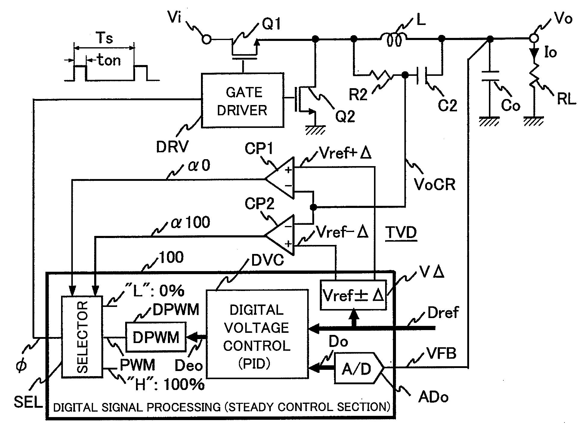
[0048]FIG. 1 is a diagram showing a circuit configuration of a digital control switching power-supply device according to a first embodiment. In FIG. 1, reference character Vi denotes an input terminal, and reference character Vo denotes an output terminal. A high-side power MOSFET Q1 is connected to the input terminal Vi, and a low-side power MOSFET Q2 is connected to the ground. An LC smoothing filter, which is a power system output filter composed of an inductor L and a capacitor Co, and a CR filter composed of a resistor R2 and a capacitor C2 are connected to a midpoint between the power MOSFETs Q1 and Q2 at one ends thereof. The other end of the CR filter composed of the resistor R2 and the capacitor C2 and the output terminal Vo are connected to a midpoint of the LC smoothing filter, and a digital voltage control means DVC is also connected to the midpoint of the LC smoothing filter via an A / D converter ADo in a digital signal processing section 100. The capacitor Co of the LC...

second embodiment

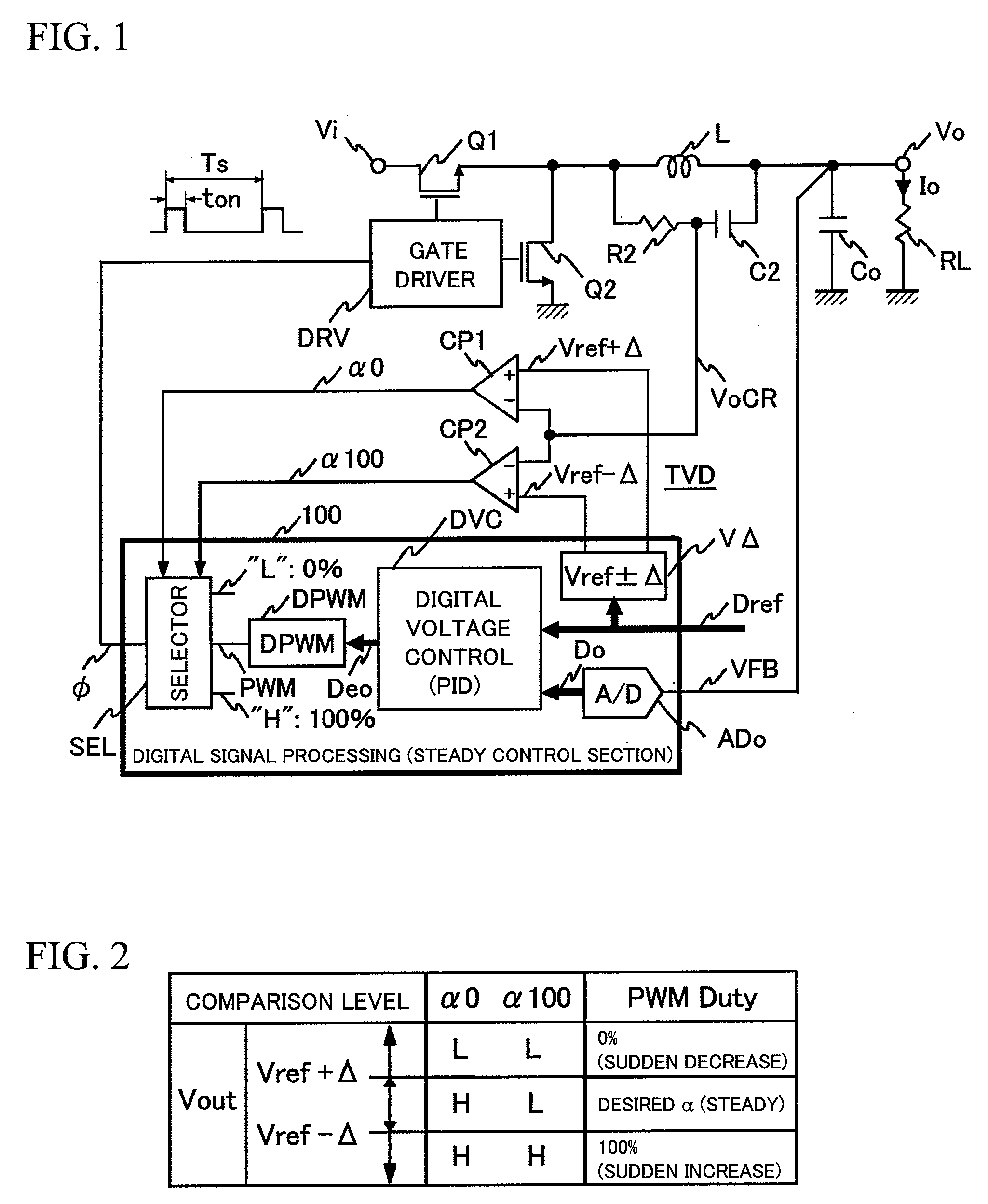
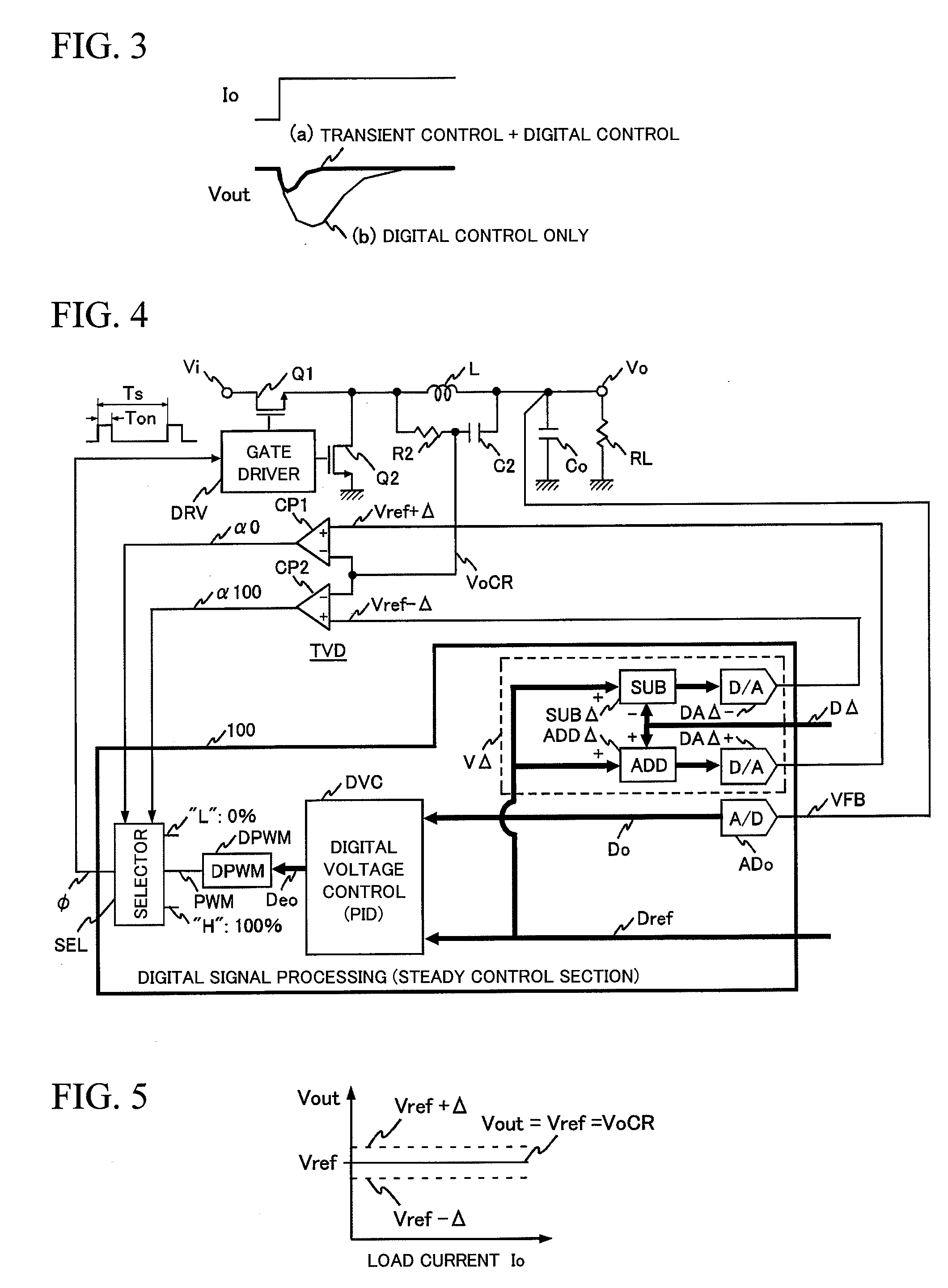
[0065]For easy understanding of the operation of the power supply, in the first embodiment described above, the transient variation detection width Δ is centered around the reference voltage Vref. Therefore, as shown in FIG. 5, the relationship between the output voltage Vout at the output terminal Vo and the output voltage VoCR of the CR filter for transient variation detection is fixed independently of the magnitude of the load current Io. Since the inductor L actually has an equivalent series resistance (ESR) (not shown), the output voltage VoCR tends to increase as the load current Io increases as shown in FIG. 6, while the output voltage Vout is controlled to be a fixed value. Thus, it is necessary that the transient variation detection width Δ is set taking into account the output voltage VoCR of the CR filter, which is a ramp voltage.

[0066]It is known that the ramp output voltage VoCR of the CR filter is expressed as ESR* Io. In actual, however, the ramp voltage cannot be dir...

third embodiment

[0072]With reference to FIG. 8, a third embodiment will be described. FIG. 8 shows a circuit configuration in which the digital voltage control means DVC performs the arithmetic operation using the digital reference voltage signal Dref and a signal obtained by digitizing the output voltage VoCR of the CR filter for transient variation detection. The circuit configuration shown in FIG. 8 differs from that shown in FIG. 7 in that, instead of the output voltage Vout at the output terminal Vo, the output voltage VoCR of the CR filter is under the fixed value control to be used as the reference voltage Vref. As shown in FIG. 9, as the load current Io increases, the output voltage Vout decreases. This is an implementation of functions referred to as active droop and active voltage positioning, which use the ESR of the inductor L.

[0073]According to the third embodiment described above, fast transient response or the like can be achieved as in the embodiments described earlier. In addition,...


PUM


Abstract

To provide a digital control switching power-supply device capable of suitably achieving fast transient response at the time of a sudden load change. In parallel with normal digital signal processing means that outputs a PWM pulse signal having a desired duty, transient variation detection means composed of a CR filter provided across an output inductor and a window comparator is provided in preparation for a sudden load change. If a sudden decrease in load is detected, a PWM pulse signal having a duty of 0% is forcedly output, and if a sudden increase in load is detected, a PWM pulse signal having a duty of 100% is forcedly output.

Description

BACKGROUND OF THE INVENTION[0001]1. Field of the Invention[0002]The present invention relates to a digital control switching power-supply device for setting an output voltage at a reference voltage of a command signal and information processing equipment provided with the digital control switching power-supply device.[0003]2. Background Art[0004]As disclosed in the JP Patent Publication (Kokai) No. 2003-61351, when a conventional digital control switching power-supply device detects a sudden load change, it copes with the sudden load change by generating a sudden load change PWM pulse signal by switching a control gain of digital voltage control means, which corresponds to an analog control error amplifier.SUMMARY OF THE INVENTION[0005]According to the method described in the JP Patent Publication (Kokai) No. 2003-61351, a pair of power semiconductor switching components is driven under the control of digital voltage control means and a DPWM generator, which carry out digital signal...

Claims


Application Information

Patent Timeline
Patent Type & Authority Applications(United States)
IPC IPC(8): G05F1/575
CPCH02M3/157
Inventor SASE, TAKASHIKAWAKUBO, YOSUKE
Owner HITACHI LTD
Why Eureka
Try Eureka