Terahertz-Band Optical Filter, Designing Method Thereof, and Manufacturing Method Thereof

a filter and terahertz-band technology, applied in the field of bandpass filters, can solve the problems of difficult to obtain a stable temperature characteristic and tend to attenuate the transmittance, and achieve the effects of excellent impedance matching with an external electric field, and reducing the increase in the optical path length of the cavity

Inactive Publication Date: 2008-10-16
MURATA MFG CO LTD
View PDF5 Cites 8 Cited by
  • Summary
  • Abstract
  • Description
  • Claims
  • Application Information

AI Technical Summary

Benefits of technology

[0053]According to the present invention, the matching layer is formed from a pair consisting of a ¼ wavelength low refractive index layer and a ¼ wavelength high refractive index layer. In particular, by forming a layer disposed at an end of the structure using a low refractive index layer, excellent impedance matching with an external electric field can be obtained.
[0054]In addition, one or more adjustment layers having an optical path length of a ½ wavelength of a passband center frequency and formed from a low refractive index medium are disposed at either end of the multi-cavity structure between the cavity layer and the matching layer. The adjustment layers are coupled with a coupling layer therebetween, the coupling layer has an optical path length of a ¼ wavelength of a passband center frequency, and the coupling layer is formed from a high refractive index medium. In this way, the intensity of a spurious component occurring in the stopbands at either end of the passband caused by an increase in the optical path length of a cavity can be reduced.
[0055]Furthermore, one or more second adjustment layers having an optical path length of one wavelength of a passband center frequency and formed from a low refractive index medium are disposed between the multi-cavity structure and the adjustment layer and between the cavity layer and the adjustment layer, and the second adjustment layers are coupled with a coupling layer therebetween. The coupling layer has an optical path length of a ¼ wavelength of a passband center frequency, and the coupling layer is formed from a high refractive index medium. In this way, the intensity of a spurious component occurring in the stopbands at either end of the passband caused by an increase in the optical path length of a cavity can be reduced.
[0056]Still furthermore, by changing the optical path length of the layer of the high refractive index medium of the matching layer to an integer multiple of a ⅛ wavelength of a passband center frequency, the second-order Fabry-Perot component appearing on the high-frequency side of the main passband can be reduced.
[0057]Yet still furthermore, by forming a laminated structure by stacking dielectric ceramic raw sheets of at least two types having a refractive index ratio of 2 or more together, and subsequently, firing the laminated structure at one time, the terahertz band optical filter can be produced at a production cost lower than those in existing manufacturing methods. Thus, the terahertz band optical filter can be mass-produced with excellent industrial productivity.
[0058]Since the optical path length of the multi-cavity structure is determined when the terahertz band optical filter is designed, the passband width in a predetermined range can be determined by the optical path length of the cavity layer. By using this method, even when a design change in the bandwidth is carried out, a variation in transmittance caused by the design change can be reduced.

Problems solved by technology

However, in that filter, the transmittance tends to attenuate as the target frequency increases.
However, only a few types of material having a low τε are available for the high refractive index medium.
As a result, like the above-described Q problem, in the structure in which a high refractive index material is used for part of the cavity layer, it is difficult to obtain a stable temperature characteristic.

Method used


Image

  • Terahertz-Band Optical Filter, Designing Method Thereof, and Manufacturing Method Thereof
  • Terahertz-Band Optical Filter, Designing Method Thereof, and Manufacturing Method Thereof
  • Terahertz-Band Optical Filter, Designing Method Thereof, and Manufacturing Method Thereof

Examples


first embodiment

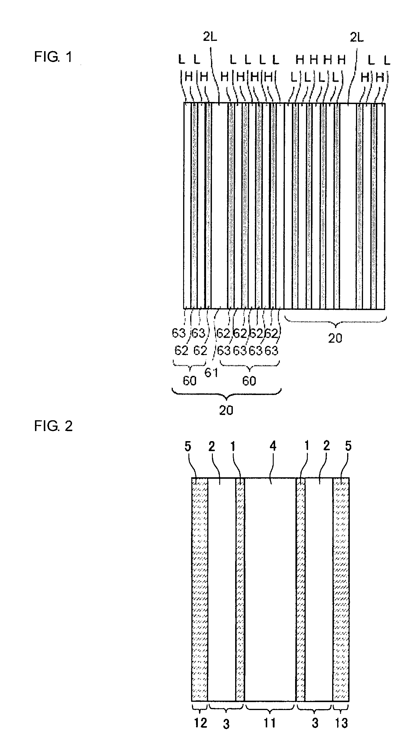
[0098]A terahertz band optical filter according to a first embodiment is described below with reference to FIGS. 2 and 3. FIG. 2 is a cross-sectional view of the terahertz band optical filter according to a first embodiment.

[0099]This terahertz band optical filter includes a first cavity layer 11 formed from a low refractive index medium (a low dielectric constant medium) 4 and having an optical path length of a multiple integer of λO / 2, a basic grating 3 including a layer formed from a high refractive index medium (a high dielectric constant medium) 1 and having an optical path length of λO / 4 and a layer formed from a low refractive index medium 2 and having an optical path length of λO / 4, and a second cavity layer 12 and a third cavity layer 13 each formed from a high refractive index medium 5 and having an optical path length of a multiple integer of λO / 2.

[0100]As shown in FIG. 2, the high refractive index media 1 of the basic gratings 3 are disposed at either end of the first ca...

second embodiment

[0109]A terahertz band optical filter according to a second embodiment is described next with reference to FIGS. 4 to 6.

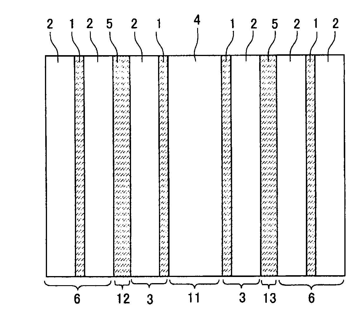
[0110]FIG. 4 is a cross-sectional view of the terahertz band optical filter according to a second embodiment. The structure of this terahertz band optical filter includes the structure of the first embodiment as a basic structure. Other basic gratings 6 are further added at either end of the basic structure.

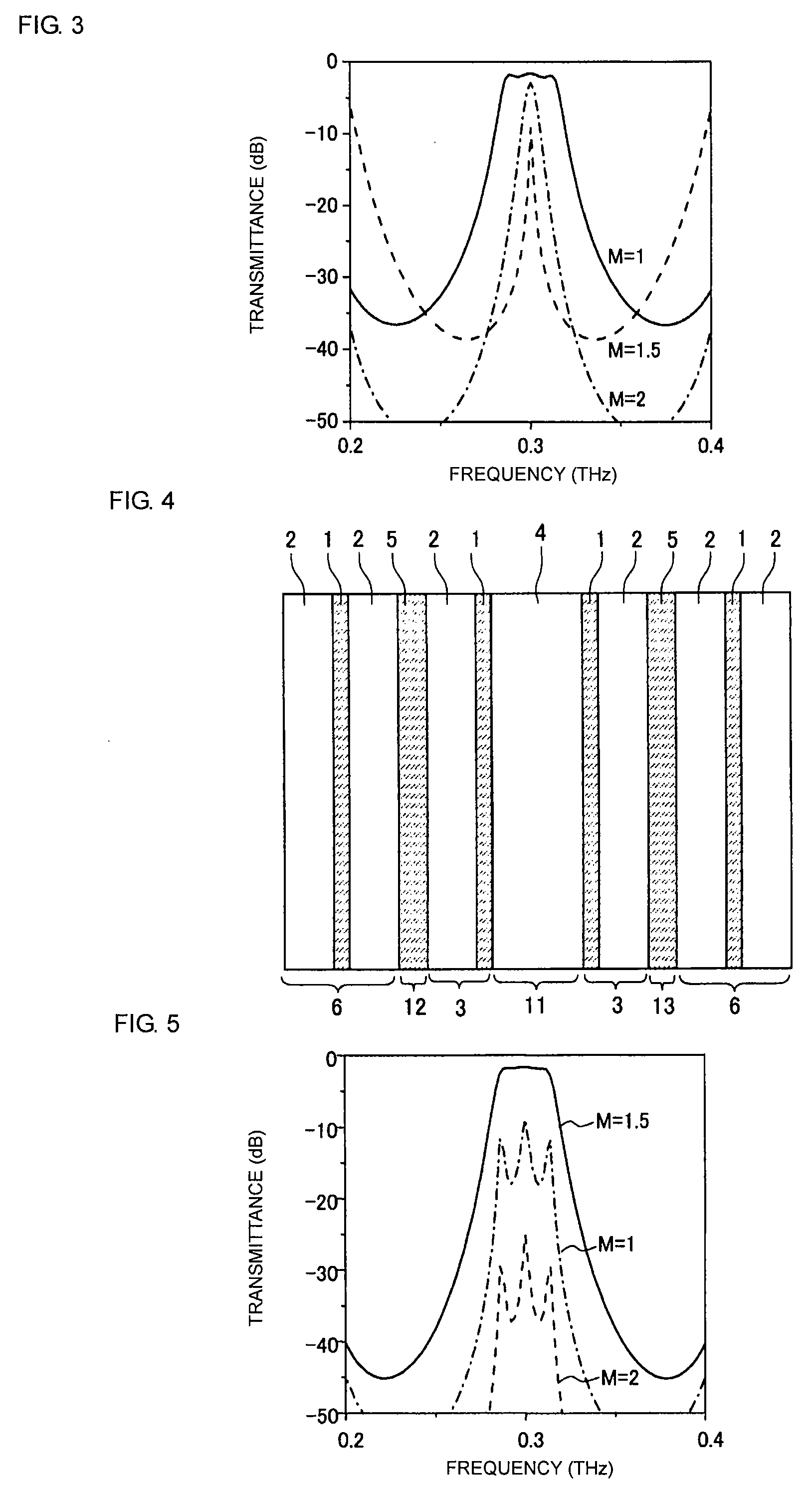
[0111]As shown in FIG. 4, a layer of the high refractive index medium 1 and a layer of the low refractive index medium 2 each having an optical path length of a ¼ wavelength and having a refractive index ratio of 2 or more are alternately stacked in three layers (the number of pairs M=1.5) so that the basic grating 6 is achieved. In this example, since the second cavity layer 12 and the third cavity layer 13 are formed from the high refractive index medium 5, a layer of the high refractive index medium 1 is sandwiched by layers of the low refractive index medium...

third embodiment

[0120]A terahertz band optical filter according to a third embodiment is described next with reference to FIG. 7. In the third embodiment, a method for changing a passband width by setting the optical path length of the first cavity layer of the first and second embodiments to an integer multiple of λO / 2 is described.

[0121]FIG. 7 illustrates a change in a −3 dB passband width when the optical path length of the first cavity layer in the multi-cavity structure according to the first embodiment is changed from λO / 2 to 3λO.

[0122]As can be seen from FIG. 7, as the optical path length of the first cavity layer is increased by an integer multiple of λO / 2, the bandwidth of the passband decreases. In this example, when the optical path length is λO / 2, the bandwidth is about 13% of the central wavelength λO. However, when the optical path length is increased to 3λO, the bandwidth can be decreased to about 6% of the central wavelength λO.

[0123]By using this effect, the passband width of the f...


PUM


Abstract

A terahertz band optical filter having a dielectric multilayer periodic structure in which a plurality of dielectric materials are periodically layered. Multi-cavity layers each having an optical path length of n times λ/2 (n is an integer greater than or equal to 1) and made of a low-refractive index medium are arranged. The cavity layers are coupled using a single-layer coupling layer having an optical path length λ/4 and made of a high-refractive index medium, thus forming a multi-cavity structure. Matching layers each including a high refractive index layer and a low refractive index layer each having an optical path length of λ/4 are disposed at either end of the multi-cavity structure.

Description

CROSS REFERENCE TO RELATED APPLICATIONS[0001]The present application is a continuation of International Application No. PCT / JP2006 / 319935, filed Oct. 5, 2006, which claims priority to Japanese Patent Application No. JP2005-379548, filed Dec. 28, 2005, and Japanese Patent Application No. JP2006-152711, filed May 31, 2006, the entire contents of each of these applications being incorporated herein by reference in their entirety.FIELD OF THE INVENTION[0002]The present invention relates to a bandpass filter that allows electromagnetic waves in a desired frequency range in a terahertz band to pass therethrough and, in particular, a terahertz band optical filter having a dielectric multilayer periodic structure in which a plurality of dielectric materials are periodically layered, a method for designing the terahertz band optical filter, and a method for manufacturing the terahertz band optical filter.BACKGROUND OF THE INVENTION[0003]A multi-cavity filter has been known as an optical filt...

Claims


Application Information

Patent Timeline
Patent Type & Authority Applications(United States)
IPC IPC(8): G02B5/28B05D5/06
CPCG02B5/204
Inventor MATSUMOTO, NAOKI
Owner MURATA MFG CO LTD
Why Eureka
Try Eureka