Stripping apparatus for the gas-solid separation process in a fluidized bed

a technology of gas-solid separation and stripping apparatus, which is applied in separation processes, lighting and heating apparatus, furnaces, etc., can solve the problems of increasing the deactivation of catalysts, mechanical wearout on processing units, and reducing process efficiency, so as to facilitate gas-solid contact and maximize stripping volume. , the effect of preventing the formation of stagnation zones

Inactive Publication Date: 2008-10-16
PETROLEO BRASILEIRO SA (PETROBRAS)
View PDF7 Cites 9 Cited by
  • Summary
  • Abstract
  • Description
  • Claims
  • Application Information

AI Technical Summary

Benefits of technology

[0011]The baffle-plates are perforated with holes, in a circular or elliptical geometry, uniformly sized and distributed on the surface area of the plates where the holes are positioned offset in relation to the holes of the parallel, sequential baffle-plates, which leads to a homogeneous fluid flow and maximization of the stripping volume within the stripping chamber.
[0012]In this way, the stripping apparatus maximizes the stripping volume while prevents the formation of stagnation zones in the stripping chamber.
[0013]Moreover, the stripping apparatus promotes bubble-breaking of the vaporized stripping fluid that rise in counter-current flow, which facilitates gas-solid contact necessary to the gas-solid separation process.
[0014]Also, the stripping apparatus provides a reduction of erosion damage in the perforated plates, as long as the circular or elliptical geometry of the holes does not generate points of stress in the material used in their manufacture.

Problems solved by technology

Poor stripping reduces the efficiency of the process beyond causing higher temperatures in the regeneration stage, increasing the deactivation of the catalyst and the mechanical wear out on the processing unit.
However, the geometry of the segmented baffle-plates, as proposed, does not eliminate the central stagnation zones, which results in a reduced stripping volume.
Also, the segmentation does not allow for manufacturing baffle-plates in sizes suitable for industrial application.

Method used


Image

  • Stripping apparatus for the gas-solid separation process in a fluidized bed
  • Stripping apparatus for the gas-solid separation process in a fluidized bed
  • Stripping apparatus for the gas-solid separation process in a fluidized bed

Examples


Embodiment Construction

[0020]In a gas-solid separation process in a fluidized bed within a stripping chamber, the contact occurs between a fluidized solid particles and a gaseous flowing stripping fluid, in a counter-current flow.

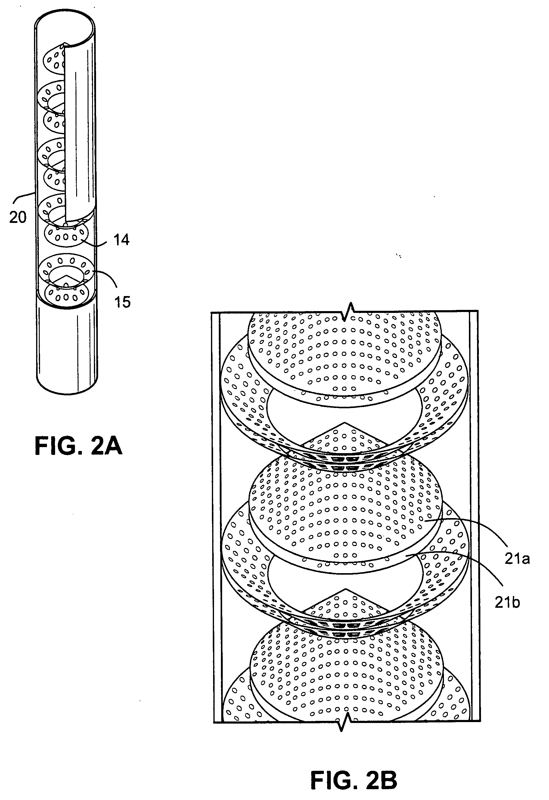
[0021]The stripping apparatus of this invention is described below, with the aid of the annexed figures, for an implementation applied in the gas-solid separation process in a petroleum refining fluid catalytic cracking unit—FCCU.

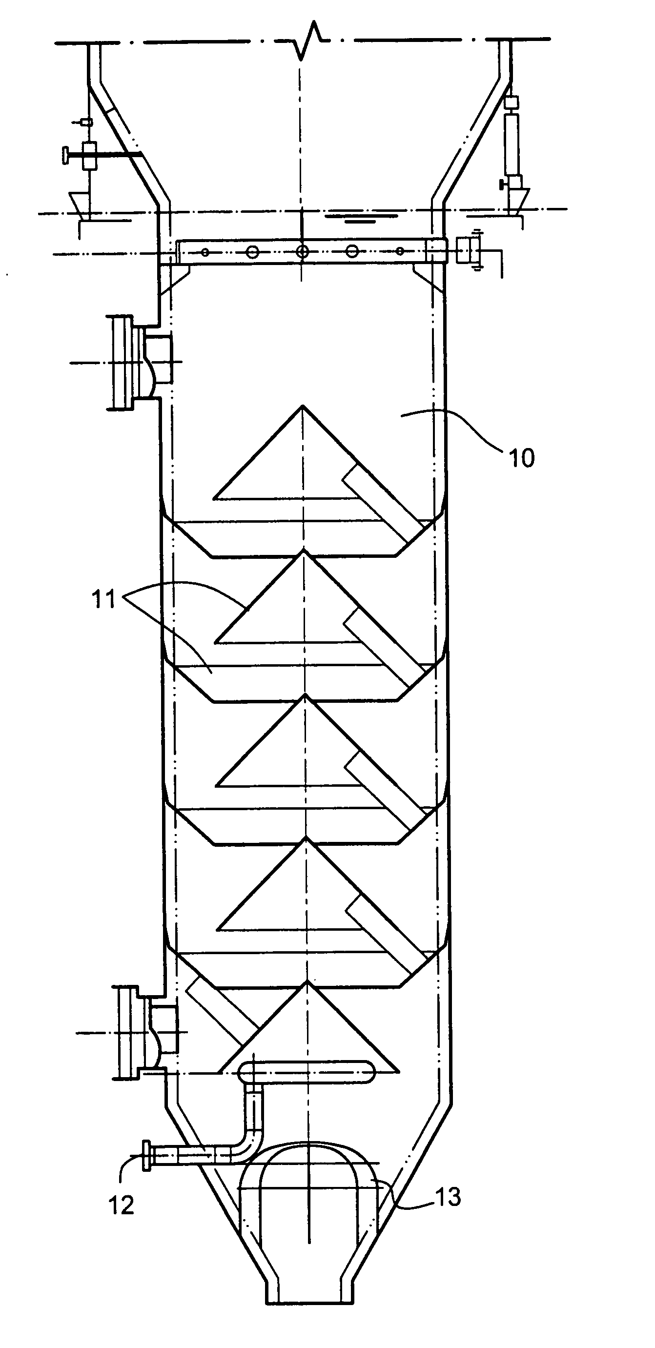
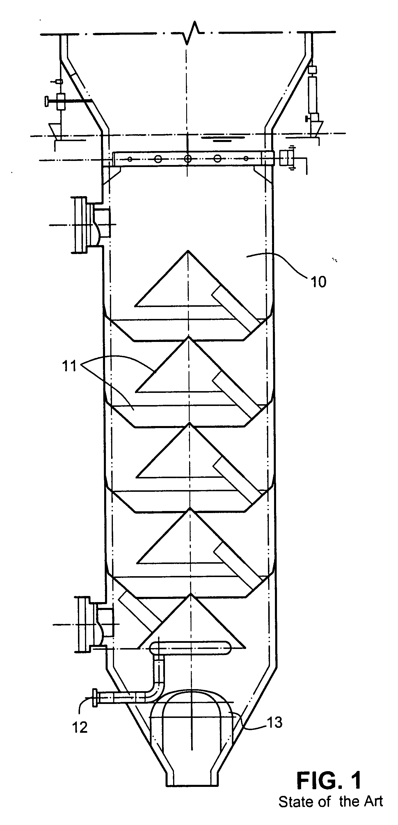
[0022]FIG. 1 shows the parts of a stripper like those used inside a separator vessel (not shown) of an FCCU.

[0023]an approximately vertical stripping chamber (10);

[0024]baffle-plates (11), laid out in series;

[0025]fluid distributor (12) to feed the stripping fluid;

[0026]grids (13) to collect the refractory waste and coke;

[0027]A stripping process in a FCCU means stripping hydrocarbons from a fluidized bed of solid catalyst particles in which a stripping fluid and a particulate catalyst containing adsorbed hydrocarbons are placed in contact in an approxim...


PUM


Abstract

A stripping apparatus is described for the gas-solid separation process in a fluidized bed in a counter-current flow of a stripping fluid. The apparatus includes sets of perforated baffle-plates with holes, fixed in series, alternating central and lateral plates inside a stripping chamber. The holes in the baffle-plates, in number, size and in circular or elliptical lay-out, are oriented in offset position in relation to the holes in the parallel and subsequent baffle-plates, reducing the damage of erosion on the perforated baffle-plates and optimizing stripping of the fluidized solid particles.

Description

FIELD OF THE INVENTION[0001]The present stripping apparatus for gas-solid separation process in a fluidized bed belongs to the field of equipments for the removal of components adsorbed on porous solid particles, in contact with a counter-current flow stripping fluid, such as found in a fluid catalytic cracking unit—FCCU in petroleum refining. More specifically, it refers to a device that includes perforated baffle-plates with holes, in serial sets, fixed inside a stripper. The geometry, distribution, and size of the holes enhance process efficiency and lower erosion damage on the baffle-plates subjected to the impact of fluidized particles.BACKGROUND OF THE INVENTION[0002]Inside a stripper, a gas-solid separation process in a fluidized bed is basically a mass transfer process between a gaseous stripping fluid flowand a fluidized bed of solid particles.[0003]In the petroleum refining, the purpose of the catalyst stripper of fluid catalytic cracking unit—FCCU is to remove the hydroca...

Claims


Application Information

Patent Timeline
Patent Type & Authority Applications(United States)
IPC IPC(8): B01J8/18
CPCB01D53/12B01J8/0065B01J8/18
Inventor HUZIWARA, WILSON KENZOBAPTISTA, CLAUDIA MARIA DE LACERDA AVARENGACERQUEIRA, HENRIQUE SOARESFUSCO, JOSE MOZART
Owner PETROLEO BRASILEIRO SA (PETROBRAS)
Why Eureka
Try Eureka