System for applying a continuous surface layer on porous substructures of turbine airfoils

a technology of airfoil and surface layer, applied in the direction of machine/engine, heat inorganic powder coating, metal rolling stand, etc., can solve problems such as the likelihood of failure, and achieve the effect of enhancing mechanical connection

Inactive Publication Date: 2008-10-16
SIEMENS ENERGY INC
View PDF28 Cites 15 Cited by
  • Summary
  • Abstract
  • Description
  • Claims
  • Application Information

AI Technical Summary

Benefits of technology

[0003]This invention relates to a coating system for attaching a surface layer to a foam material. In at least one embodiment, the coating system may be usable as a component of a cooling system of a turbine engine. The coating system may include preparing an outer surface of the foam such that at least a portion of the porous structure forming the foam material extends outwardly from a plane in which an outer surface of filler in the foam material resides. The surface layer is attached to the outer surface and to exposed portions of the porous structure, which enables an enhanced mechanical connection between the surface layer and the foam material.
[0006]An advantage of this invention is that at least a portion of the porous structure forming the metal foam may be exposed and protrude from an outer surface of the filler in the foam, thereby enabling the surface layer to be attached to the metal foam, at least in part, due to the mechanical interaction with the portions of the porous structure extending outwardly from the outer surface of the filler. Such a configuration significantly increases the ability of the surface layer to remain attached to the porous structure.

Problems solved by technology

In addition, turbine vanes and blades often contain cooling systems for prolonging the life of the vanes and blades and reducing the likelihood of failure as a result of excessive temperatures.

Method used


Image

  • System for applying a continuous surface layer on porous substructures of turbine airfoils
  • System for applying a continuous surface layer on porous substructures of turbine airfoils
  • System for applying a continuous surface layer on porous substructures of turbine airfoils

Examples


Embodiment Construction

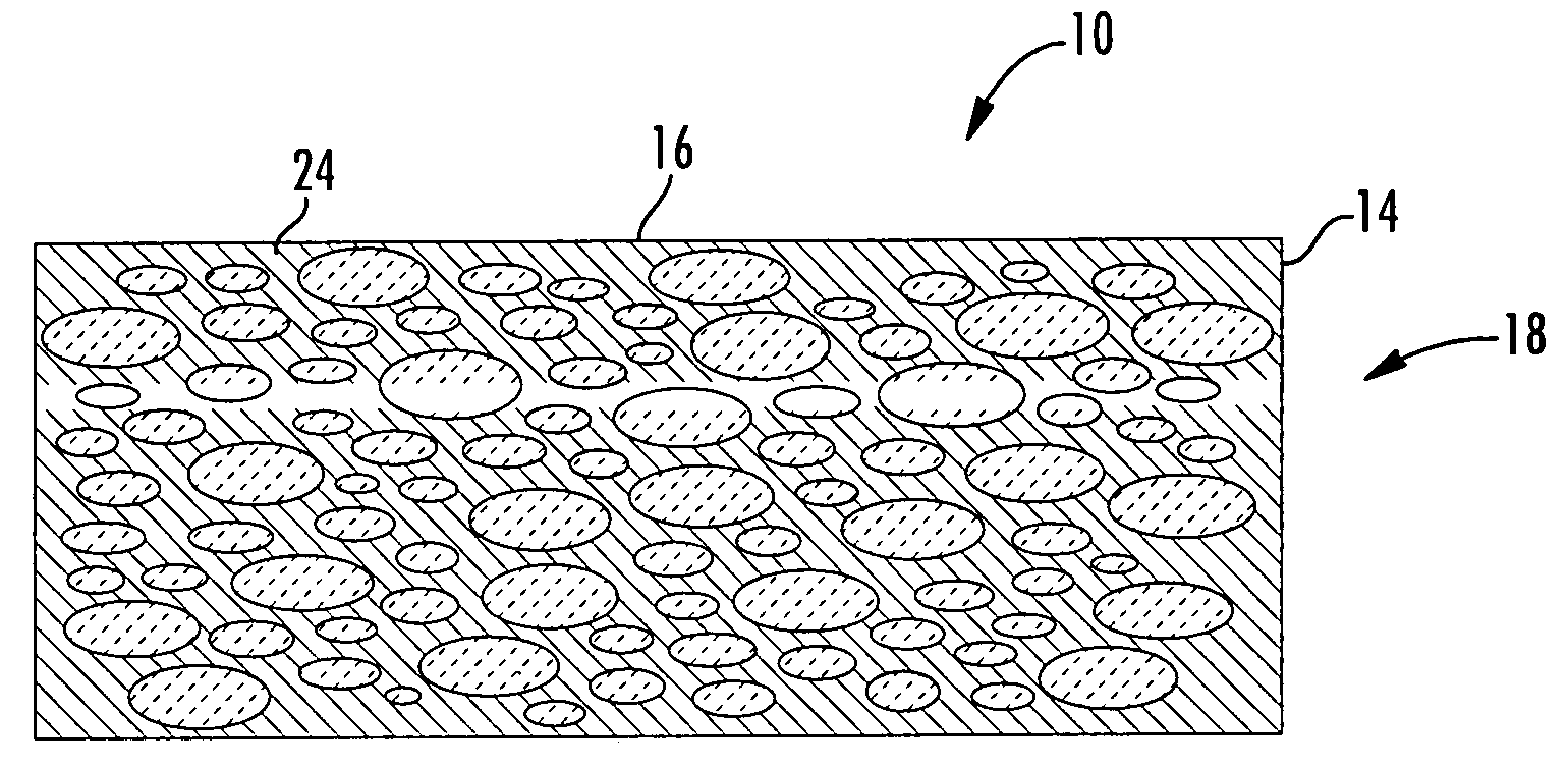
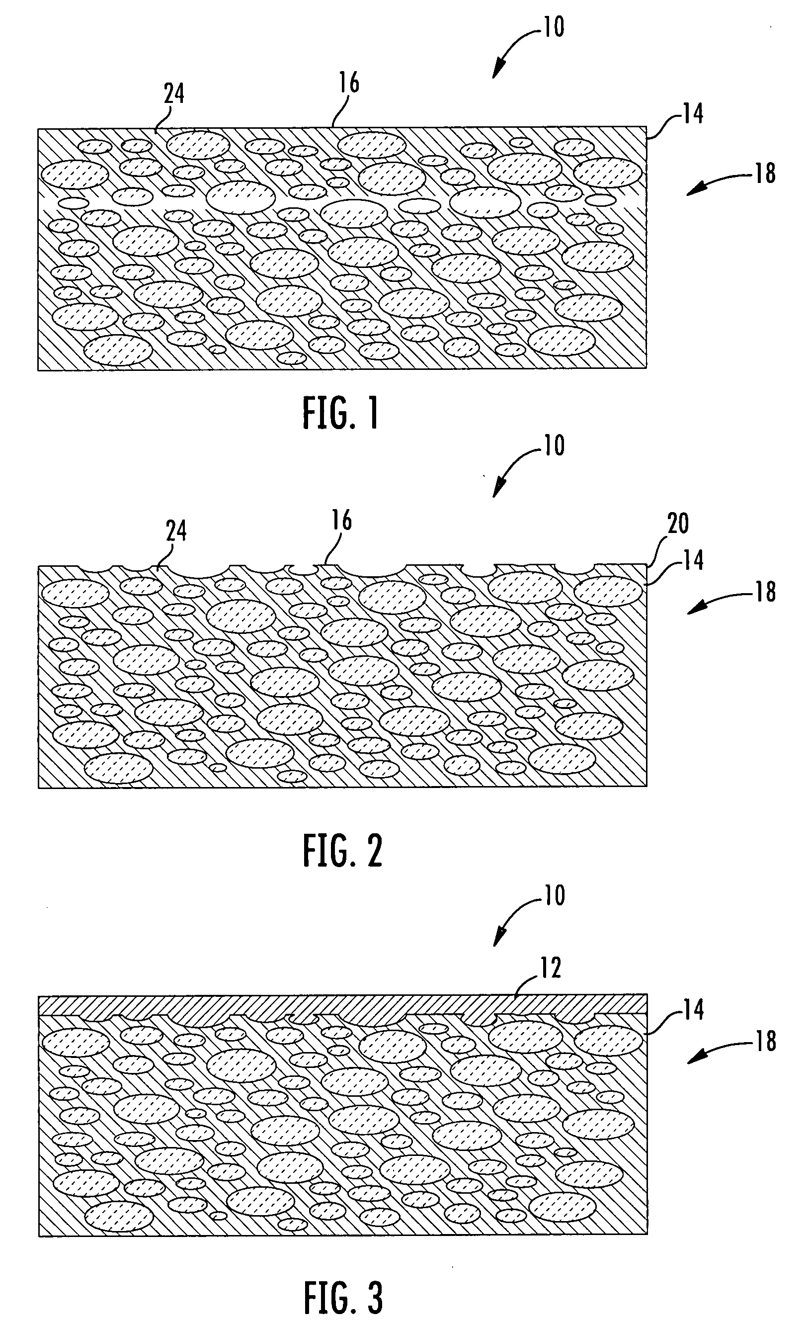
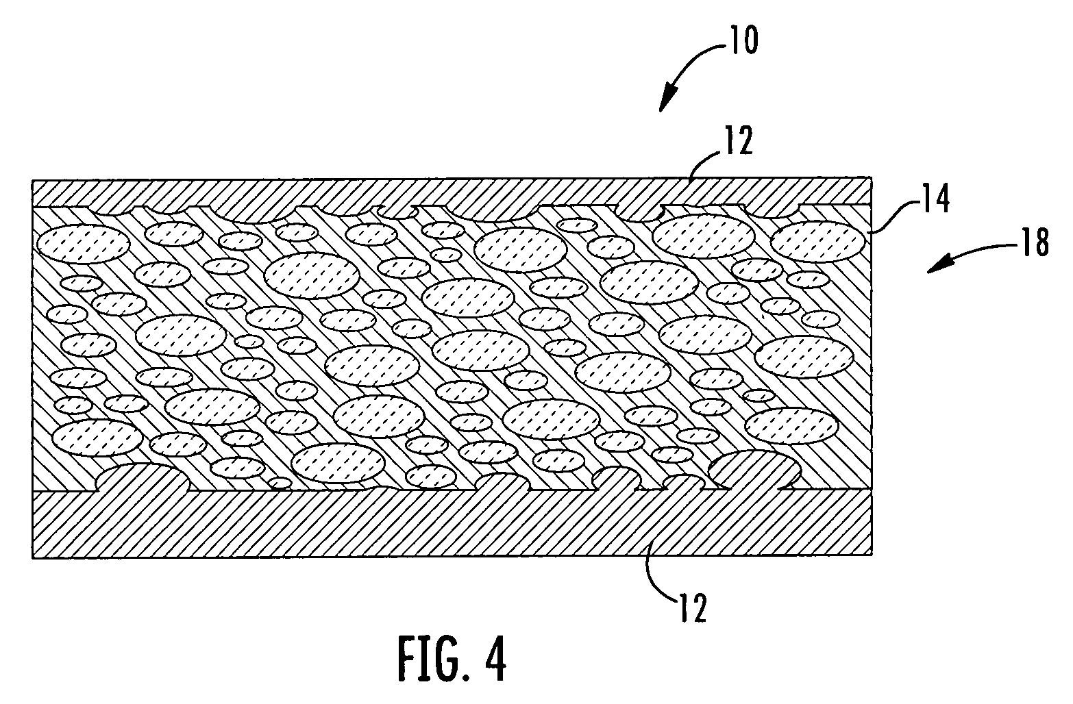
[0013]As shown in FIGS. 1-4, this invention is directed to a coating system 10 for attaching a surface layer 12 to a foam material 14. In at least one embodiment, the coating system 10 may be usable as a component of a cooling system of a turbine engine. The coating system 10 may include preparing an outer surface 16 of the foam 14 such that at least a portion of the porous structure 18 forming the foam material 14 extends outwardly from a plane 20 in which an outer surface 16 of the foam material 14 resides. The surface layer 12 is attached to the outer surface 16 and exposed portion of the porous structure 18, which enables an enhanced mechanical connection between the surface layer 12 and the foam material 14.

[0014]The coating system 10 may include a foam material 14, as shown in FIG. 1. The foam material 14 may include a porous structure 18 in which there exists a plurality of open pores. The porous structure 18 may be formed from a nickel based superalloy, FeCrAl, or other appr...


PUM

PropertyMeasurementUnit
temperaturesaaaaaaaaaa
pressuresaaaaaaaaaa

Abstract

A system for forming a surface coating on an outer surface of a foam for use with cooling system of turbine engines. The system may include removing filler from the outer surface of the foam to expose a porous structure of the foam, whereby portions of the porous structure extend outwardly from a newly formed outer surface of the filler. A surface layer may be applied to the outer surface of the filler and exposed portions of the porous structure, whereby the surface layer is attached to the porous structure at least in part due to mechanical interaction with the portions of the porous structure extending outwardly from the newly formed outer surface of the filler. The filler material may then be removed from the porous structure.

Description

FIELD OF THE INVENTION[0001]This invention is directed generally to coatings applied to metal foams, and more particularly to coatings applied to metal foams usable with cooling systems of turbine airfoils.BACKGROUND[0002]Typically, gas turbine engines include a compressor for compressing air, a combustor for mixing the compressed air with fuel and igniting the mixture, and a turbine blade assembly for producing power. Combustors often operate at high temperatures that may exceed 2,500 degrees Fahrenheit. Typical turbine combustor configurations expose turbine vane and blade assemblies to these high temperatures. As a result, turbine vanes and blades must be made of materials capable of withstanding such high temperatures. In addition, turbine vanes and blades often contain cooling systems for prolonging the life of the vanes and blades and reducing the likelihood of failure as a result of excessive temperatures. Many conventional cooling systems of turbine airfoils are formed of th...

Claims


Application Information

Patent Timeline
Patent Type & Authority Applications(United States)
IPC IPC(8): B32B3/26B05D5/00
CPCB22F7/002Y10T428/12451B22F2999/00C23C24/02C23C24/08F05B2230/40F05B2230/90F05C2253/14B22F7/06Y10T29/49982Y10T428/12479Y10T428/12042Y10T29/49337Y10T29/49993B22F3/15Y10T428/249953Y10T428/249957
Inventor JAMES, ALLISTER W.ARRELL, DOUGLAS J.
Owner SIEMENS ENERGY INC
Why Eureka
Try Eureka