Battery including a fluid manager

a fluid manager and battery technology, applied in the field of fluid regulating systems, can solve the problems of limited maximum discharge rate, reduced material content, and reduced material content of oxygen reduction electrodes

Inactive Publication Date: 2008-10-16
EVEREADY BATTERY CO INC
View PDF46 Cites 39 Cited by
  • Summary
  • Abstract
  • Description
  • Claims
  • Application Information

AI Technical Summary

Benefits of technology

[0017]The disclosed technology further relates to a method of providing a battery cell, the method comprising: providing a cell housing comprising at least one fluid entry port; providing a first electrode material and disposing the first electrode material within the cell housing to form a first electrode; providing a second electrode material and disposing the second electrode material within the cell housing to form a second electrode; providing a fluid regulating system to control the entry of a fluid into the cell housing, the fluid regulating system comprising (i) a valve to control the rate of passage of the fluid to one or both of the first and second electrodes, and (ii) an actuator for operating the valve, the actuator comprising at least one conducting polymer, at least one ionic polymer-metal composite, or mixtures of two or more thereof; and positioning the fluid regulating system relative to the at least one fluid entry port so that the fluid regulating system may be operated for fluid communication with the at least one fluid entry port.
[0018]The disclosed technology further relates to an actua...

Problems solved by technology

However, some materials used in oxygen reduction electrodes are not true catalysts because they can be at least partially reduced, particularly during periods of relatively high rate of discharge.
A disadvantage of these cells is that the maximum discharge rates they are capable of can be limited by the rate at which oxygen can enter the oxygen reduction electrode.
However, changing the diffusion rate of one of these gases generally affects the others as well.
Even when efforts have been made to balance the need for a high rate of oxygen diffusion and...

Method used


Image

  • Battery including a fluid manager
  • Battery including a fluid manager
  • Battery including a fluid manager

Examples


example 1

Bending / Flap Actuator

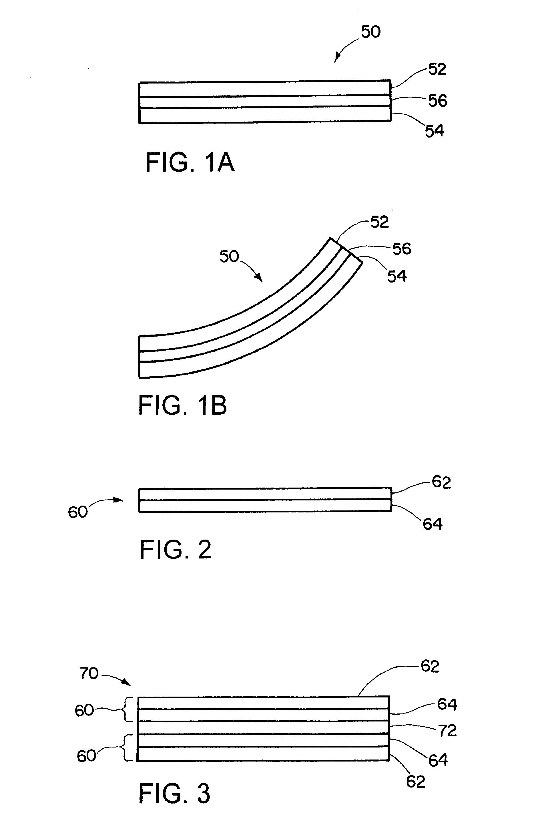
[0143]A bending / flap actuator was prepared by as follows. A trilayer was prepared by evaporating 70 nm of platinum onto opposing surfaces of a 110 μm PVDF Millipore separator. A 30 μm layer of polypyrrole was then deposited over each platinum layer. The polypyrrole layer was a polypyrrole film doped with hexafluorophosphate (PF6−) ions. The polypyrrole film was deposited onto the platinum surfaces using a solution comprising 0.06M distilled pyrrole, 0.05M tetrabutylammonium hexafluorophosphate and 1% water by volume in polycarbonate. Deposition was performed galvanostatically at 0.125 mA / cm2 for a time sufficient to produce a 30 μm layer.

[0144]The actuator was actuated in an aqueous solution of sodium hexafluorophosphate (NaPF6). The voltage was stepped between 1.4 V and −1.4 V. The actuator exhibited a bending or flapping motion in response to the voltage.

[0145]Actuators in accordance with this example were also tested for their operation as a valve. Actuator s...

example 2

Encapsulated Bending / Flap Actuators

[0146]Two actuator strips were prepared as described in Example 1. The actuators were dried in air for two weeks. The ends of the actuator were compressed between two glass slides and then sprayed on both sides with a coating material. One actuator was sprayed with a silicone coating, Silicone Conformal Coating 422A (MG Chemicals), and the other actuator was sprayed with an acrylic coating, Acryl Conformal Coating 422A (MG Chemicals), to create a 2-8 μm thick coating on the outer surface of the actuators. Aqueous NaPF6 was applied to the uncoated ends of the actuator and allowed to wick down the length of the actuator. The actuators were cycled from 1.4 to −1.4V. The silicone coated actuator was successfully actuated, while the acrylic coated actuator failed to actuate since the acrylic was too rigid and did not adhere well to the actuator. The silicone coated film dried out after three hours.

example 3

Linear Actuator

[0147]Linear actuator components were prepared as follows. Films were synthesized by depositing a solution of 0.05 M tetrabutylammonium hexafluorophosphate (Aldrich 98%), 0.06 M distilled polypyrrole (Aldrich), and 1% water in polycarbonate on a glassy carbon crucible. Before deposition, the glassy carbon was polished using a one micron diamond scrub followed by polishing with jewelers' rouge. The polypyrrole-PF6 material was deposited galvanostatically at 0.125 mA / cm2 for 8 hours to produce a film with a thickness of about 11.2 μm. The dimensions of the films were about 26 mm long×4 mm wide×11.2 μm thick.

[0148]The actuator films in this example were tested with a sliding valve mechanism, as illustrated in FIGS. 24A and 24B. In this case, a lever arm 810 was attached to one end of a first metal plate 820. The first metal plate 820 was positioned adjacent to a second plate 830. The lever arm 810 included a pivot point 812 located near an end 810a of the lever arm oppos...


PUM


Abstract

An electrochemical cell having a fluid consuming electrode and a fluid regulating system for controlling the rate of entry of fluids into the cell. The fluid regulating system may include a valve for controlling the rate of entry of fluids into the cell and an actuator for operating the valve. The actuator comprises an ionic polymer that responds to changes in a potential applied across the actuator to open or close the valve. In one embodiment, the actuator comprises at least one conducting polymer. In one embodiment, the actuator comprises polypyrrole, at least one polypyrrole derivative, or mixtures of two of more thereof.

Description

CROSS-REFERENCE TO RELATED APPLICATIONS[0001]This application is entitled to the benefit of and incorporates by reference essential subject matter disclosed in Provisional Patent Application No. 60 / 911,332 filed on Feb. 19, 2003.BACKGROUND OF THE INVENTION[0002]The disclosed technology relates to fluid regulating systems for controlling the rate of entry of fluids, such as gases, into and out of electrochemical batteries and cells such as batteries and cells that employ fluid consuming electrodes, and to the batteries and cells in which such fluid regulating systems are used, particularly air-depolarized, air-assisted, and fuel cells and batteries. More particularly, the disclosed technology relates to actuators for operating a fluid regulating system to control entry of fluids into and out of batteries and cells.[0003]Electrochemical battery cells that use a fluid, such as oxygen and other gases, from outside the cell as an active material to produce electrical energy, such as air-...

Claims


Application Information

Patent Timeline
IPC IPC(8): H01M2/02H01M8/00
CPCH01M8/04089H01M8/04201H01M12/065Y02E60/50
Inventor BAILEY, JOHN C.JONES, STEVEN D.LANGAN, RICHARD A.COLE, MATTHEWWYNDHAM MADDEN, JOHN DAVID
Owner EVEREADY BATTERY CO INC
Why Eureka
Try Eureka