Articulating facet fusion screw

Active Publication Date: 2008-10-16
DEPUY SPINE INC (US)
View PDF99 Cites 197 Cited by
  • Summary
  • Abstract
  • Description
  • Claims
  • Application Information

AI Technical Summary

Benefits of technology

[0007]The devices and methods disclosed herein relate to stabilization and/or fusion of a facet joint via intra-facet placement of a screw or screw-like device including an additional stabilization feature. The intra-facet fixation and fusion screw can be adapted to include various configurations for the efficient and safe placement of the screw within the facet joint. In addition, the articulating feature of the screw takes advantage of additional anchoring available from the external features o

Problems solved by technology

Such a technique has associated with it the risk of further injury to the patient as such translamina facet instrumentation can be difficult to place in such a way that it does not violate the spinal canal and/or contact the dura of the spinal cord or the nerve root ganglia.
Further, trans-facet instrumentation has been known to create a rotational distortion, lateral of

Method used


Image

  • Articulating facet fusion screw
  • Articulating facet fusion screw
  • Articulating facet fusion screw

Examples


Example

[0041]Certain exemplary embodiments will now be described to provide an overall understanding of the principles of the structure, function, manufacture, and use of the devices and methods disclosed herein. One or more examples of these embodiments are illustrated in the accompanying drawings. Those skilled in the art will understand that the devices and methods specifically described herein and illustrated in the accompanying drawings are non-limiting exemplary embodiments and that the scope of the present invention is defined solely by the claims. The features illustrated or described in connection with one exemplary embodiment may be combined with the features of other embodiments. Such modifications and variations are intended to be included within the scope of the present invention.

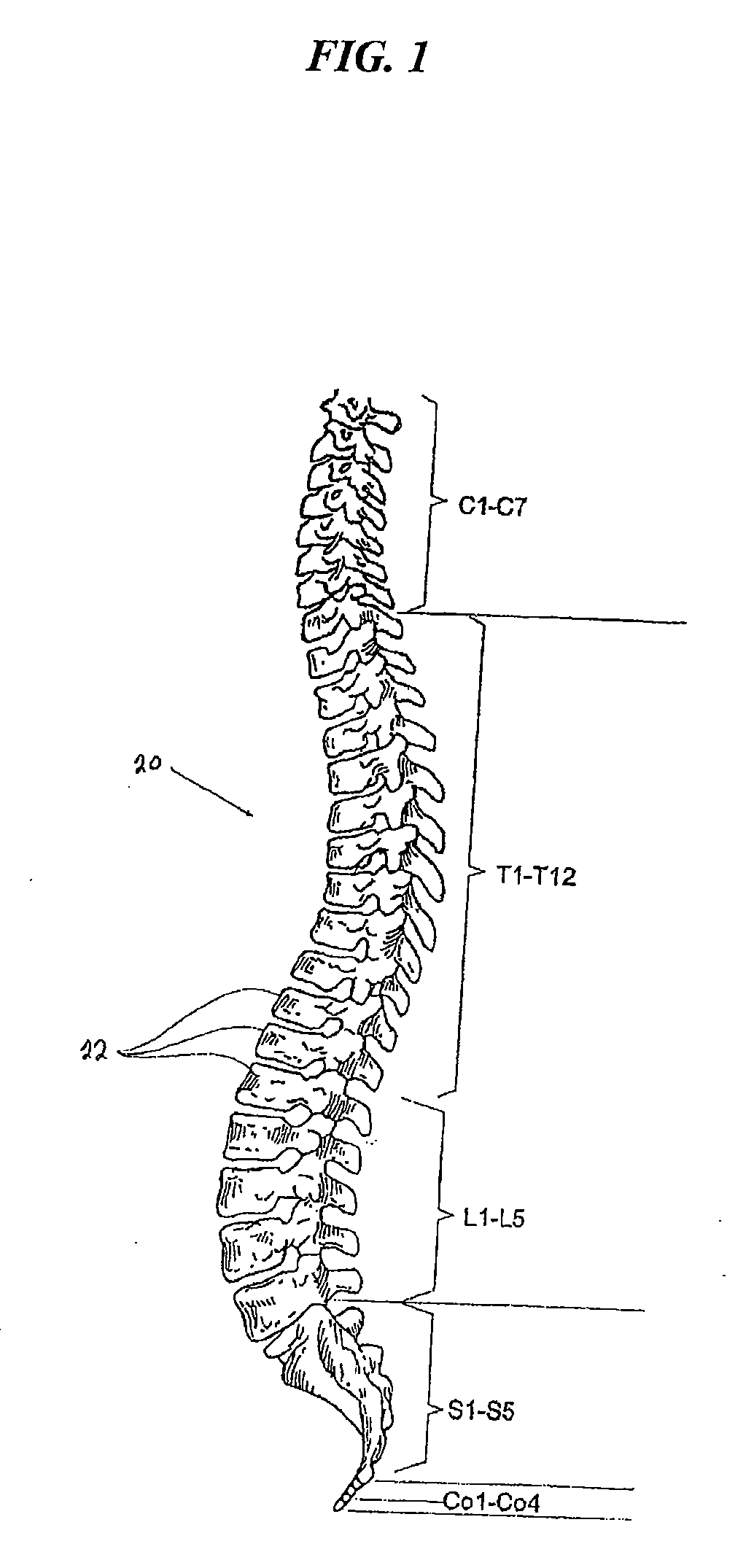
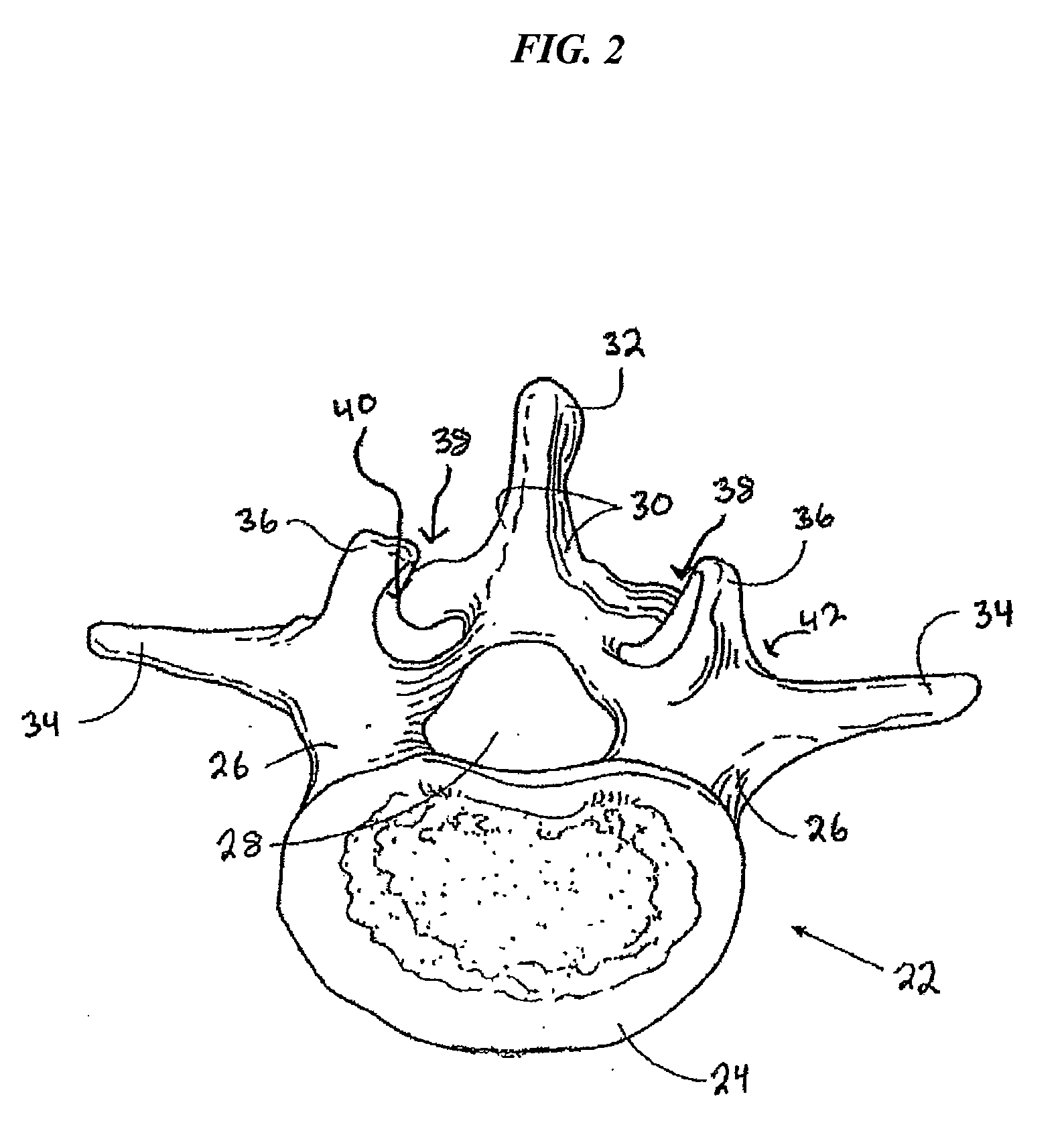
[0042]FIGS. 1-3 provide an overview of the spinal column structure and location of associated facet joints. As FIG. 1 shows, the human spinal column 20 is comprised of a series of thirty-three stacked...


PUM


Abstract

A spinal implant is provided having an elongate member with a longitudinal axis and threads extending over at least a portion of the outer surface thereof. The implant includes a stabilization feature associated with the elongate member that is selectively configurable between a delivery configuration and a deployed configuration in which the stabilization feature is oriented at an angle with respect to the longitudinal axis of the elongate member. Also, at least a portion of the implant can include a fusion-promoting bioactive material. In another aspect, the invention includes methods for providing stabilization within a facet joint by delivery of an articulating intra-facet screw.

Description

FIELD OF THE INVENTION[0001]The present invention relates to methods and devices for spinal stabilization and fusion, and particularly to stabilization and fusion of a facet joint.BACKGROUND OF THE INVENTION[0002]The vertebrae in a patient's spinal column are linked to one another by the disc and the facet joints, which control movement of the vertebrae relative to one another. Each vertebra has a pair of articulating surfaces located on the left side, and a pair of articulating surfaces located on the right side, and each pair includes a superior articular surface and an inferior articular surface. Together the superior and inferior articular surfaces of adjacent vertebra form a facet joint. Facet joints are synovial joints, which means that each joint is surrounded by a capsule of connective tissue and produces a fluid to nourish and lubricate the joint. The joint surfaces are coated with cartilage allowing the joints to move or articulate relative to one another.[0003]Diseased, d...

Claims


Application Information

Patent Timeline
IPC IPC(8): A61B17/70A61B17/58A61F2/44A61B17/04
CPCA61B17/7064A61B17/863A61B17/8685A61B2017/00004A61B2017/8655
Inventor FISHER, MICHAEL ALANMICKIEWICZ, CHRISTOPHER
Owner DEPUY SPINE INC (US)
Why Eureka
Try Eureka