Respirator and method for calibrating flow rate measuring component thereof

a flow rate and flow rate technology, applied in the field of respirators, can solve the problems of limiting the convenience, and the inability to ensure that the actual stream flow velocity coincides with the set value by controlling valves, and achieves the effect of ensuring the safety and reliability of respirators

Active Publication Date: 2008-10-23
SHENZHEN MINDRAY BIO MEDICAL ELECTRONICS CO LTD
View PDF10 Cites 22 Cited by
  • Summary
  • Abstract
  • Description
  • Claims
  • Application Information

AI Technical Summary

Benefits of technology

[0010]Therefore, an object of the present invention is to solve the above-mentioned problems in the prior art by providing a new-type respirator and a method for calibrating respiration parameters thereof that enables a user to calibrate the flow sensor conveniently as required, hence ensuring the safety and reliability of the respirator.

Problems solved by technology

However, during the operation of a respirator, a measured value and an actual value often differ greatly due to sensor aging, damage, temperature drift, water accumulation or individual variation among sensors of the same type, which are common in practical application.
However, for a commonly used anesthetic respirator actuated pneumatically and controlled electrically, it's impossible to ensure that the actual stream flow velocity coincides with the set value by controlling valves.
Since a user generally does not have any flow velocity detecting instruments matching calibration requirements, the maintenance and calibration can only be provided by the factory, which greatly limits the convenience, safety and reliability of the use of respirators.

Method used


Image

  • Respirator and method for calibrating flow rate measuring component thereof
  • Respirator and method for calibrating flow rate measuring component thereof
  • Respirator and method for calibrating flow rate measuring component thereof

Examples


first embodiment

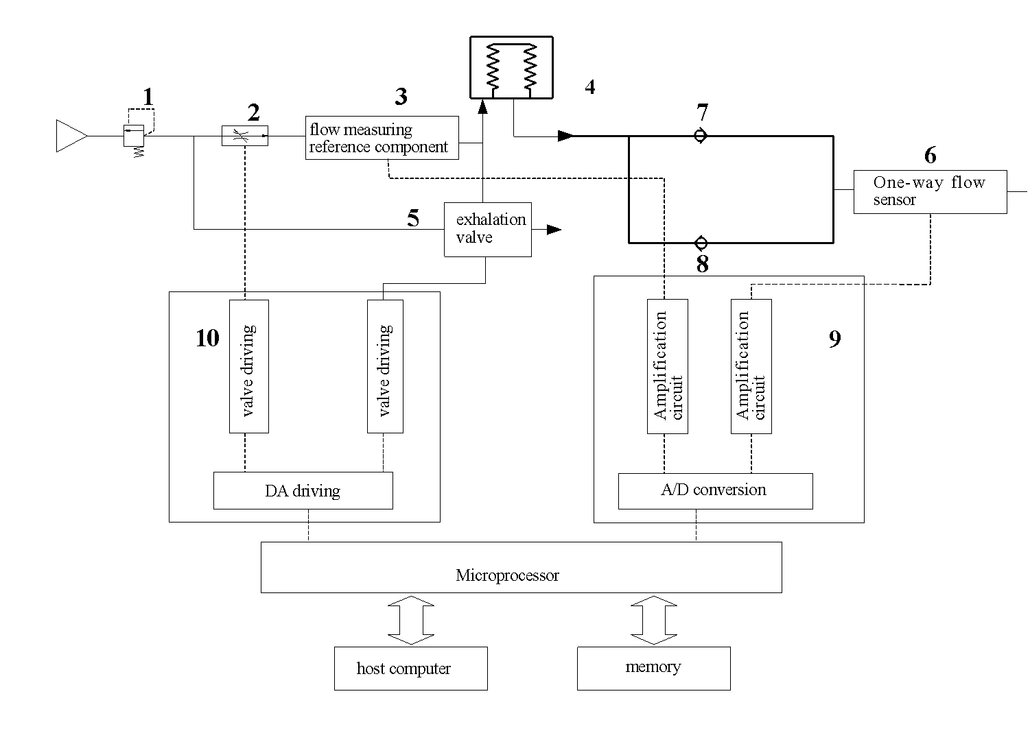
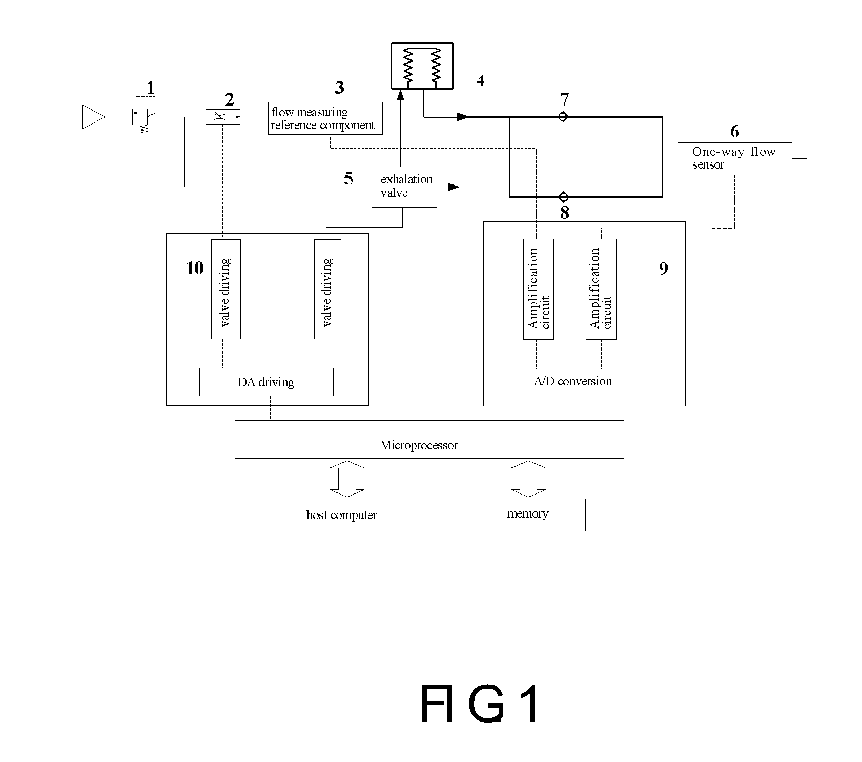
[0032]As shown in FIG. 1, a respirator according to the present invention comprises a pressure regulator 1, an inspiratory valve 2, an exhalation valve 5, a flow sensor 6, a flow measuring reference component 3, bellows 4, an inspiratory check valve 7, an expiratory check valve 8, a signal sampling and processing circuit 9 and a control circuit 10.

[0033]The inspiratory valve 2 can cause driving gas from external gas supply to be sucked in response to a control signal of the control circuit 10.

[0034]The bellows 4 is provided with a gasbag therein to which a pressure may be applied by the driving gas sucked into the bellows so as to compress fresh gases in the bag to be discharged.

[0035]The inspiratory check valve 7 operates to let the discharged fresh gas flow forward the patient.

[0036]The flow sensor 6 adopted in this embodiment is a one-way flow sensor that detects the flow rate of fresh gas flowing from the inspiratory check valve to the patient, to provide respiration parameters ...

second embodiment

[0050]As shown in FIG. 3, the present embodiment has substantially the same configuration as that of the first embodiment of the present invention except that the flow sensor 6 is a bidirectional flow sensor. Therefore components identical or similar to those of the first embodiment will not be described again.

[0051]Since the flow sensor 6 is a bidirectional flow sensor, it can detect gas flow rates of both inhalation and exhalation of the patient.

[0052]When the flow sensor 6 is a bidirectional flow sensor, it is arranged near the patient as shown in FIG. 3. A bidirectional flow sensor can measure the gas flow rate flowing into any one of the two ports thereof, however rate measurements in the two directions, that is, the directions of flowing into one port and the other, have certain difference and a doctor may place the bidirectional flow sensor randomly in use. Therefore, as compared with a one-way flow sensor, a relation between measurements, such as output voltages, and the flo...

third embodiment

[0063]As shown in FIG. 5, the respirator of the present embodiment has substantially the same configuration as that of the first embodiment of the present invention except that the flow measuring reference component 3 is provided between the bellows 4 and the inspiratory check valve 7. Therefore, the calibration process for the flow sensor 6 of the present embodiment is the same as that of the first embodiment. Components that are identical or similar to those of the first embodiment will not be described again.

Modifications of the Invention

[0064]In the embodiments of the present invention, a flow sensor is used as the flow measuring component, however the present invention is not limited thereto. Any flow sensors that are capable of measuring gas flow rate, including common pressure type flow sensors and hot filament flow sensors, can be used for the above mentioned flow measuring component and the flow measuring reference component, in which a differential pressure type flow senso...


PUM


Abstract

A respiration apparatus and a method for calibrating respiration parameters thereof are provided. A flow measuring reference component arranged behind the inspiratory valve in the ventilator is used as a flow measuring reference sensor for calibrating the flow sensor so that the flow rates of the gas through the flow measuring reference component and the flow sensor to be calibrated are identical or in a corresponding relation. Electrical parameters output from the flow sensor and the flow measuring reference component are respectively acquired and processed to obtain a relation curve of the gas flow rate and the electrical parameter of the flow sensor on the basis of the read gas flow rate and the electrical parameters of the flow sensor. The present invention enables automatic calibration for a flow sensor without using any measuring instrument.

Description

TECHNICAL FIELD[0001]The present invention relates to a respirator for assisting a patient's breathing, and more particularly, to a respirator that calibrates a flow sensor for monitoring respiration mechanics parameters therein and a method for calibrating a flow sensor thereof.DESCRIPTION OF PRIOR ART[0002]A respirator, also known as a ventilator, is a facility to implement mechanical ventilation for assisting and controlling a patient's breathing, improving his or her oxygenation and ventilation, reducing work by respiratory muscles, supporting circulatory functions and also for treating a respiratory failure. Respirator apparatus for assisting a patient's breathing, such as anesthetic machines are often used in medical treatment depending on a patient's medical condition. An anesthetic machine functions to provide inhalation anesthesia and mechanical ventilation for a patient during an operation. Since an effective implementation of mechanical ventilation necessitates an accurat...

Claims


Application Information

Patent Timeline
Patent Type & Authority Applications(United States)
IPC IPC(8): A61M16/00
CPCA61M16/0051A61M16/0075A61M16/01A61M2016/0033A61M2016/0036A61M2205/50A61M2205/702A61M16/0081A61M16/204A61M16/205A61M16/024
Inventor HUANG, LINTAOLI, XINSHENGPAN, RUILINGZHOU, XIAOYONG
Owner SHENZHEN MINDRAY BIO MEDICAL ELECTRONICS CO LTD
Why Eureka
Try Eureka