Methods, Systems, and Devices for Energy Generation

a technology of energy generation and energy harvesting, applied in the direction of electric generator control, renewable energy generation, greenhouse gas reduction, etc., can solve the problems of increasing the acquisition and maintenance cost of real estate, affecting the amount and/or intensity of resources that can be harnessed and converted into electrical energy, and affecting the efficiency of the electrical energy conversion process. , to achieve the effect of reducing the cost and complexity of the transformer, reducing the optimal and/or constant speed of the internal fan, and reducing the interference back

Inactive Publication Date: 2008-10-23
WILSON SAMUEL B
View PDF27 Cites 76 Cited by
  • Summary
  • Abstract
  • Description
  • Claims
  • Application Information

AI Technical Summary

Benefits of technology

[0040]The system can be designed to adapt to different fluid flow conditions. The duct opening (inlet), by being able to adapt to different external fluid flow conditions, is capable of achieving optimal and/or constant speed of the internal fan regardless of external fluid flow conditions. Maintaining or controlling power output by maintaining a constant and/or optimal rpm for the turbine can resu

Problems solved by technology

Larger devices, however, may lead to greater safety concerns, noise concerns, and can even be an aesthetic eyesore to some.
Additionally, because devices for harnessing wind and water power are typically exposed to the elements, such devices are usually situated out in the open.
As a result of using larger devices to harness these natural resources, more land is typically a prerequisite to installing them, which in turn increases acquisition and maintenance costs of real estate, for example.
For example, wind and water are unpredictable energy sources, which can vary with the weather, by geographic location, and from day to day.
Even further, wind and water resources can be affected by a number of other considerations, including buildings, towers or other structures, trees, and terrain to name a few, which may interfere with the amount and/or intensity of these resources that can be harnessed and converted to electrical energy.
To date, however, this goal has not easily been achieved.
Because wind velocity and air density can be at times unpredictable and/or fluctuating, it is difficult to achieve a reasonably steady, continuous, and sufficient output of electrical power from such systems.
With respect to fluid-base

Method used


Image

  • Methods, Systems, and Devices for Energy Generation
  • Methods, Systems, and Devices for Energy Generation
  • Methods, Systems, and Devices for Energy Generation

Examples


Embodiment Construction

[0052]Reference will now be made in detail to various exemplary embodiments of the invention. It is to be understood that the following detailed description is presented for the purpose of describing certain embodiments in detail. Thus, the following detailed description is not to be considered as limiting the invention to the embodiments described. Rather, the true scope of the invention is defined by the claims.

[0053]Additionally, the following embodiments describe methods, systems, and devices for energy generation using wind as the fluid energy source. Each of the embodiments described is equally suitable for any fluid energy source, including, for example, water, whether or not such embodiments could or should be modified to suit a particular fluid-based application.

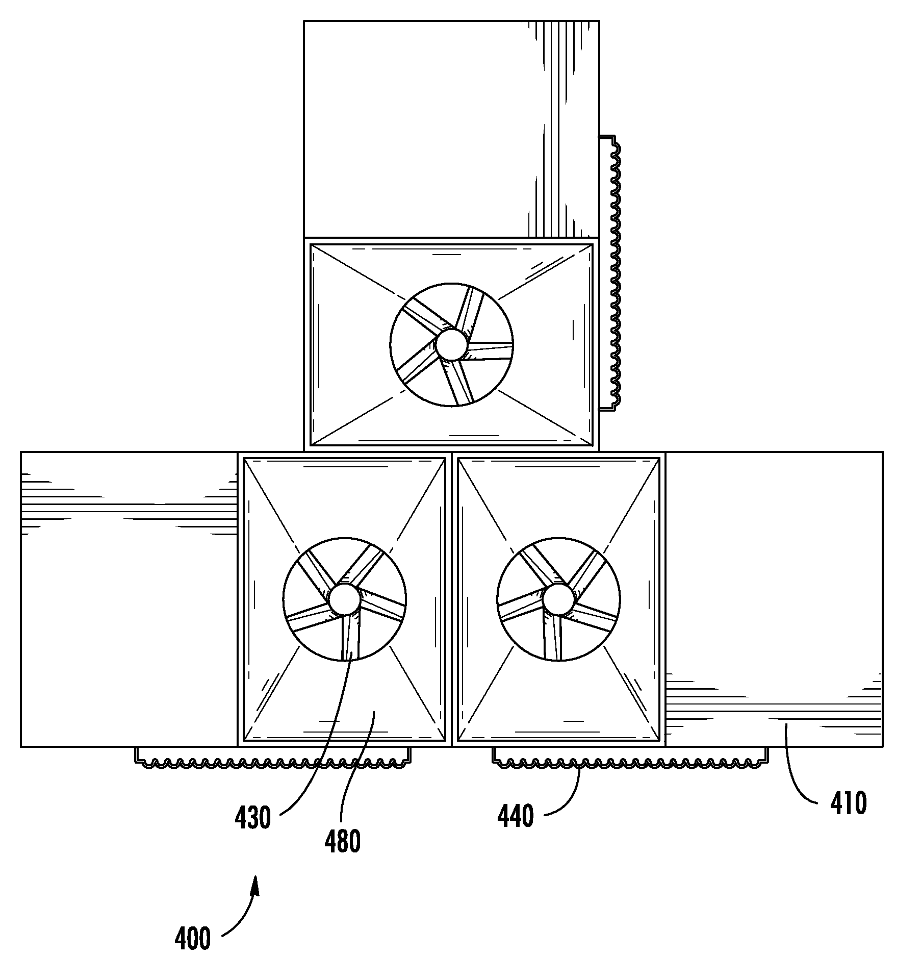
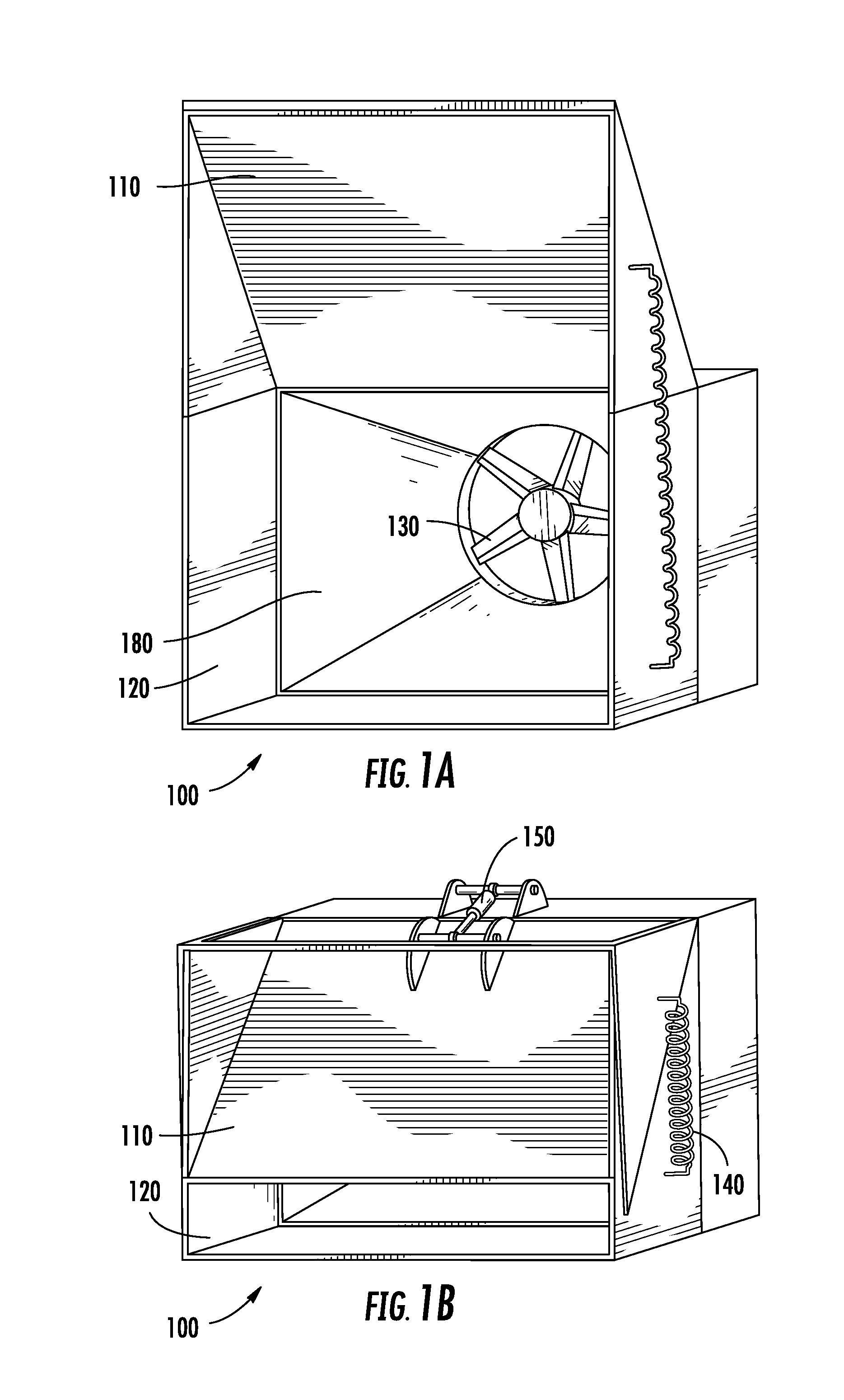
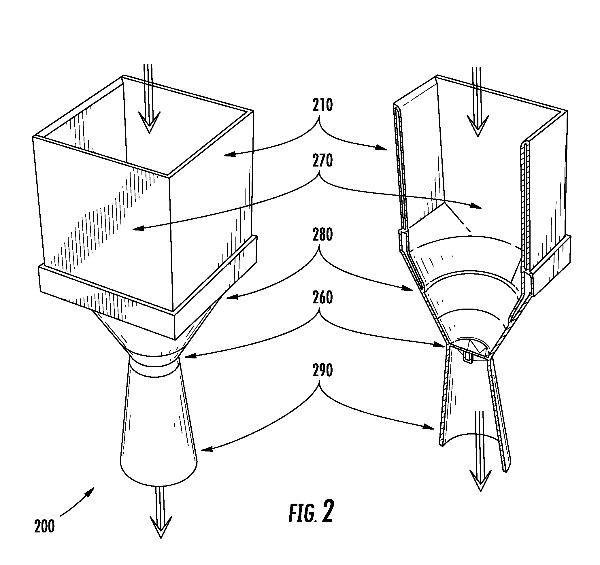
[0054]FIGS. 1 and 2 include inlets for controlling fluid flow at the fan face of a turbine. The adjustable inlets provide for the capture of an appropriate amount of air to generate relatively constant power output ...


PUM


Abstract

The present invention seeks to improve upon existing energy-generation technologies by providing methods, systems, and devices for converting mechanical power into electrical power. More specifically, the present invention relates to fluid-powered generators and methods, systems, and devices for generating power by way of such fluid-powered generators. The present invention includes devices for generating energy comprising fluid turbine generators having variable inlet(s), wherein the fluid velocity, volume, and/or mass of fluid collected by the inlet can be varied to control turbine speed to provide a reasonably steady, continuous, and/or sufficient source of energy over a wide range of conditions presented by natural fluid resources.

Description

CROSS-REFERENCE TO RELATED APPLICATIONS[0001]This application relies on the disclosure and claims the benefit of the filing date of U.S. Provisional Application No. 60 / 912,568, filed Apr. 18, 2007, the entire disclosure of which is herein incorporated by reference.BACKGROUND OF THE INVENTION[0002]1. Field of the Invention[0003]The present invention relates generally to the field of energy harvesting. More specifically, the present invention relates to the field of electrical energy generation and includes, for example, methods, systems, and devices for converting flowing fluids into electrical power. Further, for example, the present invention relates to fluid-powered generators and methods, systems, and devices for generating electrical energy with such fluid-powered generators.[0004]2. Description of Related Art[0005]There exists a continued interest around the world in the development of alternative energy sources from sources that cannot be exhausted and / or are renewable. Harnes...

Claims


Application Information

Patent Timeline
IPC IPC(8): F03B13/00F03D9/00
CPCF03B11/02F03D1/04F05B2240/12F05B2240/13Y02B10/30Y02B10/70Y02E10/226F05B2240/142Y02E10/72F03D9/32Y02E10/20
Inventor WILSON, SAMUEL B.GELHAUSEN, PAULTURNBULL, ANDREW R.STREET, TIMOTHY
Owner WILSON SAMUEL B
Why Eureka
Try Eureka