Actuator and electric toothbrush using the same

Active Publication Date: 2008-10-23
MATSUSHITA ELECTRIC WORKS LTD
View PDF6 Cites 10 Cited by
  • Summary
  • Abstract
  • Description
  • Claims
  • Application Information

AI Technical Summary

Benefits of technology

[0012]The electric toothbrush of the present invention also utilizes the electrical conducting member that contact with the shaft at the plurality of points on the

Problems solved by technology

However, since the shaft makes sliding contact with the terminal plate during the course of reciprocating movement thereof, the shaft may be flexed when a brush of the brush body is pressed against the teeth or may be shaken when it makes rec

Method used


Image

  • Actuator and electric toothbrush using the same
  • Actuator and electric toothbrush using the same
  • Actuator and electric toothbrush using the same

Examples


Example

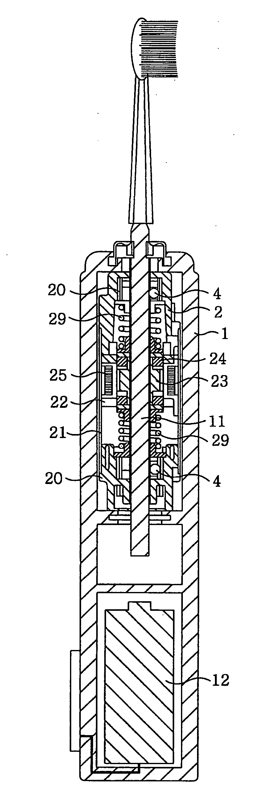
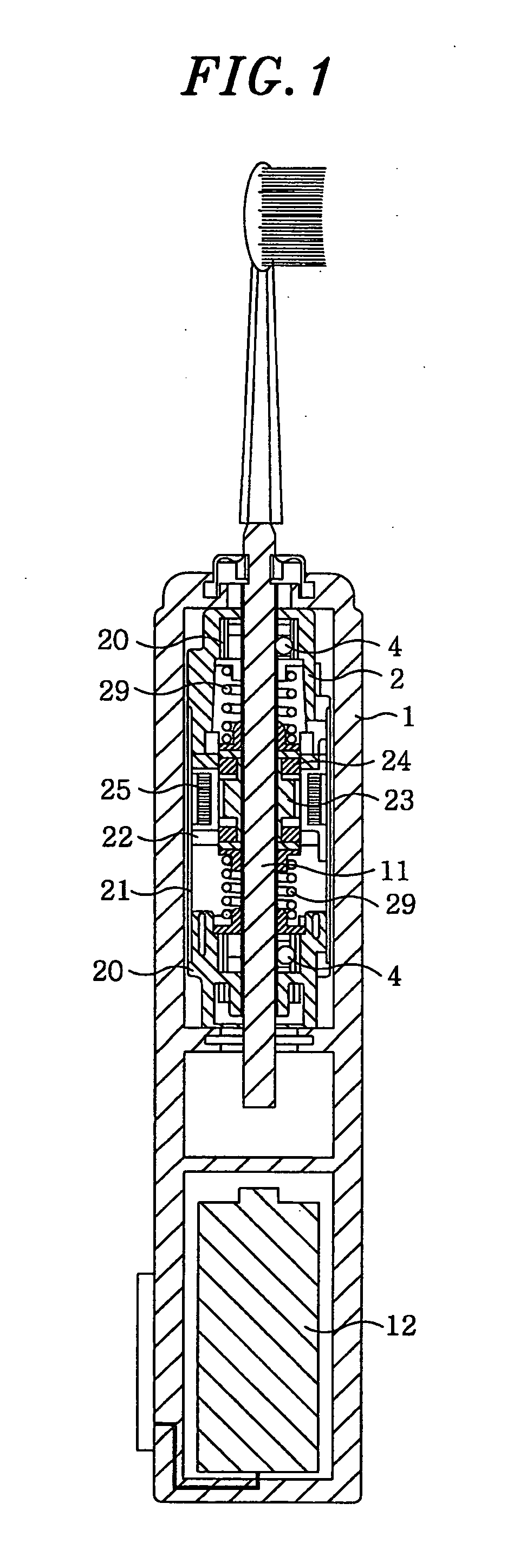
[0021]Embodiments of the present invention will be described in detail with reference to the accompanying drawings which form a part hereof. FIG. 1 is a cross sectional view showing an electric toothbrush in accordance with one embodiment of the present invention. The electric toothbrush includes a cylindrical housing 1 that accommodates an actuator such as a linear oscillating actuator 2 and a battery 12 as an electric power source. A tip end portion of a shaft 11, which is reciprocatingly driven by the linear oscillating actuator 2 in an axial direction, protrudes from a tip end of the housing 1. A brush body 5 is detachably attached to the tip end portion of the shaft 11.

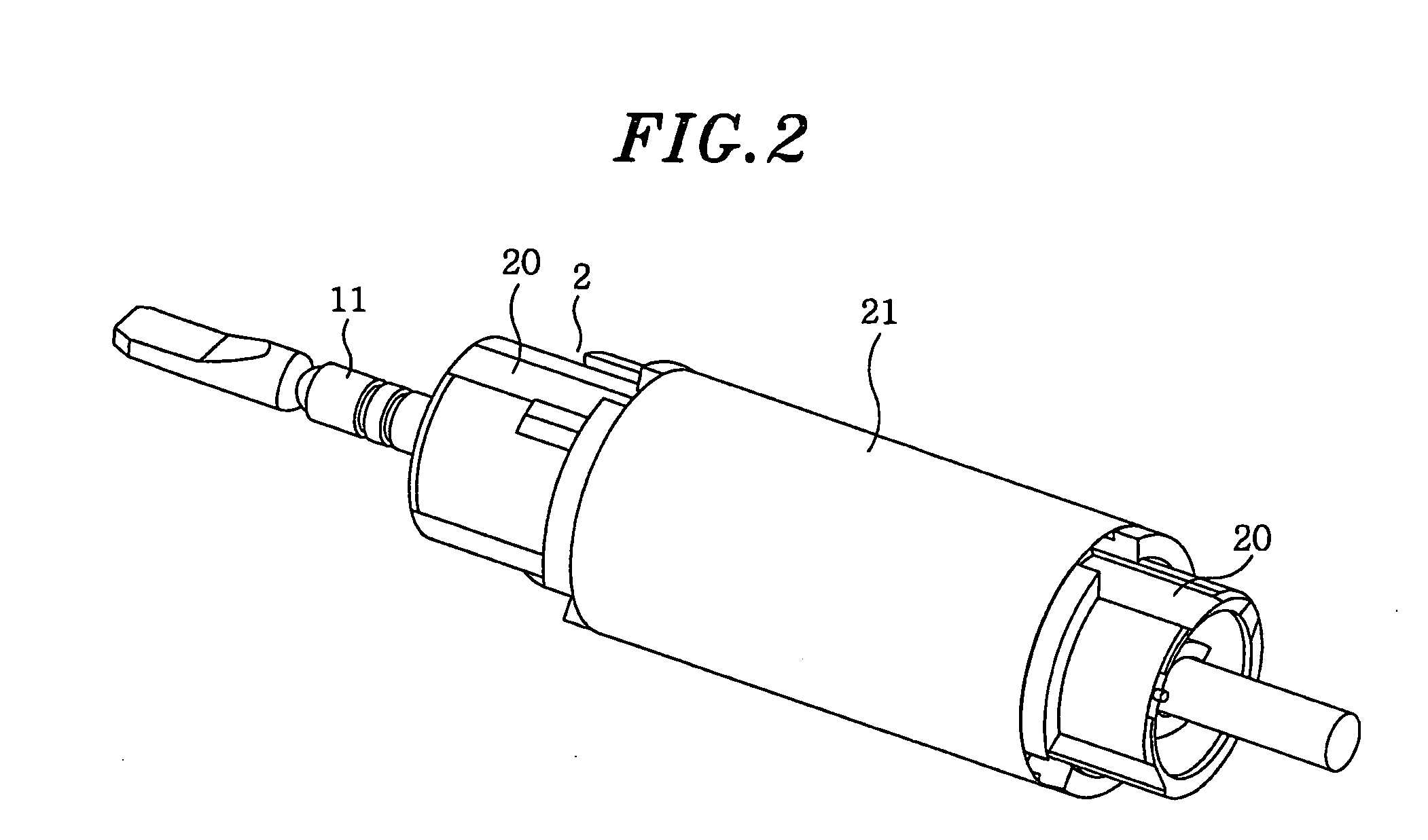
[0022]FIGS. 2 to 4 illustrate the linear oscillating actuator 2 in detail. A pair of shaft support portions 20 and 20 is disposed to support the shaft portions near the opposite ends of the shaft 11 such that the shaft 11 is axially slidable and rotatable around a longitudinal axis thereof. A cylindrical case 21 ...


PUM


Abstract

An actuator includes a shaft supported in such a manner as to make axial reciprocating movement or rotational reciprocating movement around longitudinal axis thereof, and an electricity conducting member for making contact with the shaft at a plurality of points on a circumferential surface of the shaft used as an electricity conducting path leading to other members. Further, an electric toothbrush includes the actuator as a drive power source for a brush body, and the brush body is adapted to be supplied with an electric current through the shaft.

Description

FIELD OF THE INVENTION[0001]The present invention relates to an actuator and an electric toothbrush using the actuator as a drive mechanism.BACKGROUND OF THE INVENTION[0002]There is known a toothbrush called an electric toothbrush, an ion toothbrush or an electronic toothbrush. This toothbrush is adapted to remove plague with potential gradient by allowing a weak current to flow through the body of a user to between a holder and a portion inserted into the user's mouth.[0003]An electric toothbrush having such a function is disclosed in Japanese Patent No. 2560025. This electric toothbrush includes a shaft reciprocatingly driven in an axial direction thereof, a brush body attached to a tip end of the shaft and a terminal plate connected to an electric power source. The electric toothbrush is designed to supply electricity to the brush body through the shaft by bringing the terminal plate into contact with the shaft.[0004]However, since the shaft makes sliding contact with the termina...

Claims


Application Information

Patent Timeline
IPC IPC(8): H02K41/00A46B13/00
CPCA61C17/3445A61N1/322H02K33/16A46B13/02A46B13/00
Inventor SHIMIZU, HIROAKIKUNITA, TOMOHIROTANIGUCHI, SHINICHIKISHIMOTO, SUEHISANISHINAKA, TAKAHIRO
Owner MATSUSHITA ELECTRIC WORKS LTD
Why Eureka
Try Eureka