Rotor of Rotating Electric Machine, Rotating Electric Machine and Vehicle Drive Apparatus

a technology of rotating electric machines and drive apparatuses, which is applied in the direction of hybrid vehicles, gearing, electric propulsion mounting, etc., can solve the problems of electric power loss and influence of iron loss to a considerable degree, and achieve the effect of improving energy efficiency

Inactive Publication Date: 2008-10-23
TOYOTA JIDOSHA KK
View PDF7 Cites 28 Cited by
  • Summary
  • Abstract
  • Description
  • Claims
  • Application Information

AI Technical Summary

Benefits of technology

[0017]An object of the present invention is to provide a rotor of a rotating electric machine that can implement high-speed rotations together with improved energy efficiency, as well as the rotating electric machine and a vehicle drive apparatus.
[0027]In accordance with the present invention, a vehicle drive apparatus can be implemented with which both of iron-loss reduction and enhancement of the rotor-core strength can be achieved and high-speed rotations can be achieved with improved energy efficiency.

Problems solved by technology

The copper loss refers to electric power loss due to resistance in coil windings.
If a high rpm motor is used with the purpose of increasing the output power density, influences of the iron loss increase to a considerable degree.

Method used


Image

  • Rotor of Rotating Electric Machine, Rotating Electric Machine and Vehicle Drive Apparatus
  • Rotor of Rotating Electric Machine, Rotating Electric Machine and Vehicle Drive Apparatus
  • Rotor of Rotating Electric Machine, Rotating Electric Machine and Vehicle Drive Apparatus

Examples


Embodiment Construction

[0039]The present invention is hereinafter described in detail with reference to the drawings. In the following, like or corresponding components are denoted by like reference characters and a description thereof is not repeated.

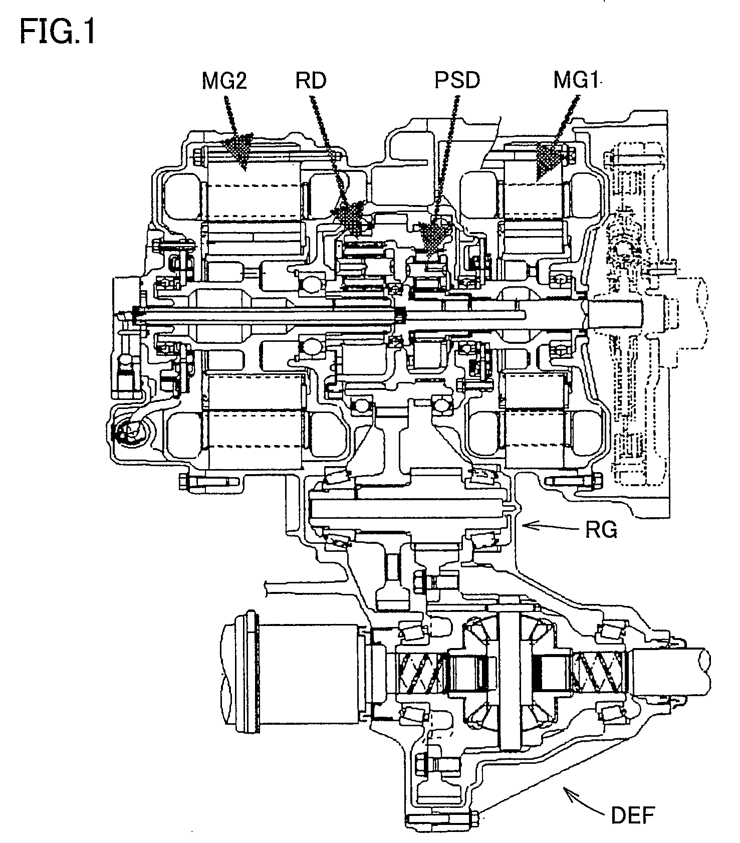
[0040]FIG. 1 is a cross-sectional view showing a structure of a vehicle drive apparatus of a hybrid vehicle according to an embodiment of the present invention.

[0041]Referring to FIG. 1, the vehicle drive apparatus includes motor generators MG1, MG2, a power split device PSD, a reduction mechanism RD, a reduction gear RG, and a differential gear DEF.

[0042]As shown in the cross section of FIG. 1, such components as motor generator MG2 operating chiefly as a motor for driving wheels, motor generator MG1 operating chiefly as an electric generator and power split device PSD are arranged on the same axis as that of an engine (not shown) so as to decrease in size and lower the center of gravity of the vehicle drive apparatus unit.

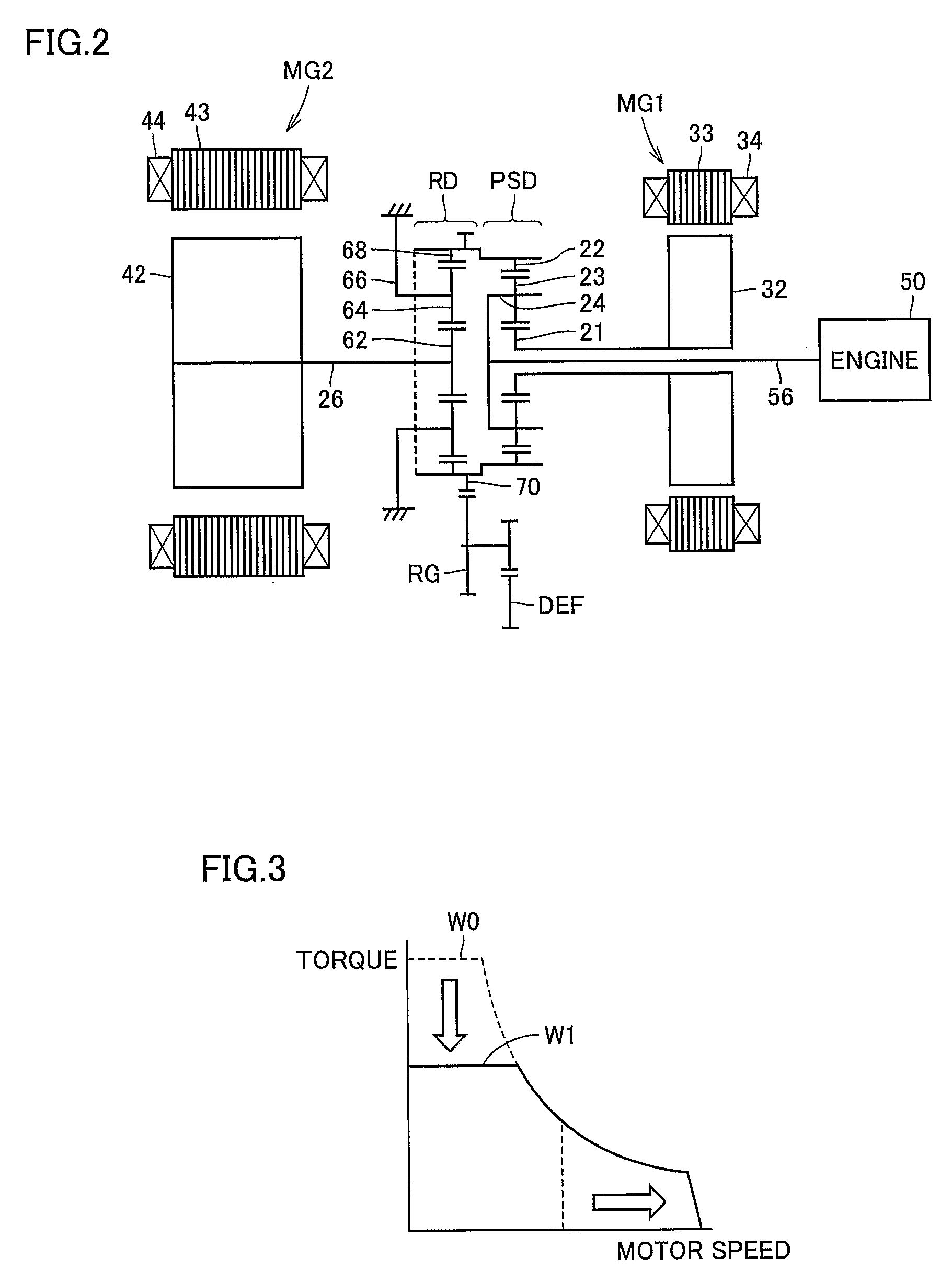
[0043]FIG. 2 is a schematic showin...


PUM


Abstract

There are provided a rotor of a rotating electric machine that can implement high-speed rotations with improved energy efficiency, as well as the rotating electric machine and a vehicle drive apparatus. The rotor of the rotating electric machine includes two magnets arranged within an electrical angle in the range of 127° to 140°, the electrical angle having its center at the center of rotations of the rotor, and the magnets being arranged along a V-shape with its acute end facing toward the center of rotations. The rotor further includes a rotor body having two openings housing the two magnets respectively. The rotor body has a support portion placed at the acute end of the V-shape and serving as a partition between the two openings.

Description

TECHNICAL FIELD[0001]The present invention relates to a rotor of a rotating electric machine, the rotating electric machine and a vehicle drive apparatus. In particular, the invention relates to a rotor of an interior permanent magnet synchronous motor, a rotating electric machine having the rotor mounted thereon, and a vehicle drive apparatus.BACKGROUND ART[0002]Recently, in terms of global warming prevention and resource conservation, the role to be fulfilled by motor vehicles has been considerably increasing in importance. For the motor vehicle, reduction of CO2 emissions requires improvement in fuel economy. The improvement in fuel economy has to be accomplished together with emissions-cleaning and safety assurance.[0003]As vehicles improved in fuel economy, fuel cell vehicles and hybrid vehicles have been of great interest. The hybrid vehicle includes as its component a gasoline engine, a transmission, an inverter, a battery, a motor as well as their controllers. Such vehicles ...

Claims


Application Information

Patent Timeline
Patent Type & Authority Applications(United States)
IPC IPC(8): H02K21/14B60K6/20
CPCB60K1/02B60K6/26B60K6/365B60K6/405B60K6/445F16H3/727H02K7/006F16H2200/2007F16H2200/2097H02K1/2766H02K21/14Y02T10/6239F16H2037/0866Y02T10/62
Inventor KAMIYA, MUNEHIRO
Owner TOYOTA JIDOSHA KK
Why Eureka
Try Eureka