Circuit and method for glitch correction

a glitch correction and circuit technology, applied in the direction of angle modulation details, electrical apparatus, angle modulation, etc., can solve the problem that the wireless communication system is not presently capable of directly processing and generating radio frequency (rf) signals

Inactive Publication Date: 2008-10-23
CONVERSANT INTPROP MANAGEMENT INC
View PDF5 Cites 14 Cited by
  • Summary
  • Abstract
  • Description
  • Claims
  • Application Information

AI Technical Summary

Benefits of technology

[0009]A simple integer boundary detection circuit and a finite impulse response (FIR) filter act in conjunction with the DSM circuitry to provide enhancements to the operation of a fractional-N PLL. The integer boundary detection circuit efficiently detects when an integer boundary has been crossed in an input signal to the DSM circuitry and applies an appropriate adjustment to a divisor signal output from the DSM circuitry only when an integer boundary has been crossed. By doing so, the filter counteracts glitches that may be generated by the DSM circuitry responsive to the crossing of the integer boundary. In effect, the step response of the DSM circuitry is approximated and corrected for using a FIR filter fed by the integer crossing detection circuit.

Problems solved by technology

Wireless communications systems are not presently capable of directly processing and generating radio frequency (RF) signals.

Method used


Image

  • Circuit and method for glitch correction
  • Circuit and method for glitch correction
  • Circuit and method for glitch correction

Examples


Embodiment Construction

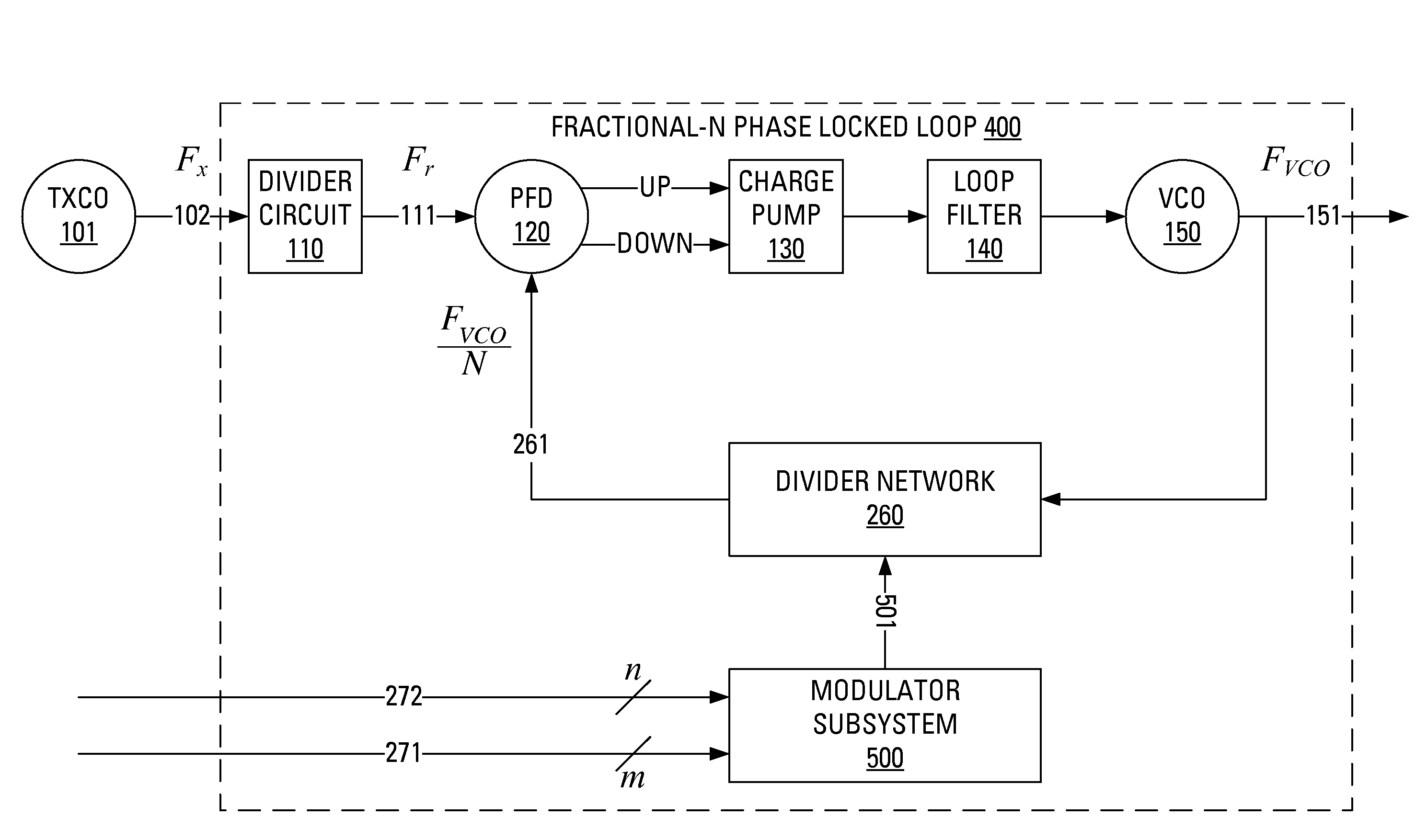
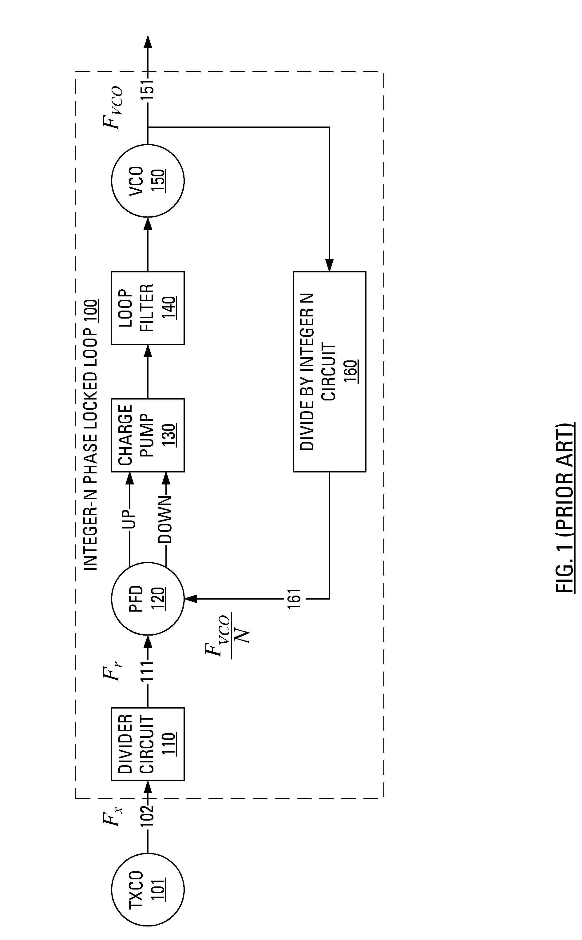
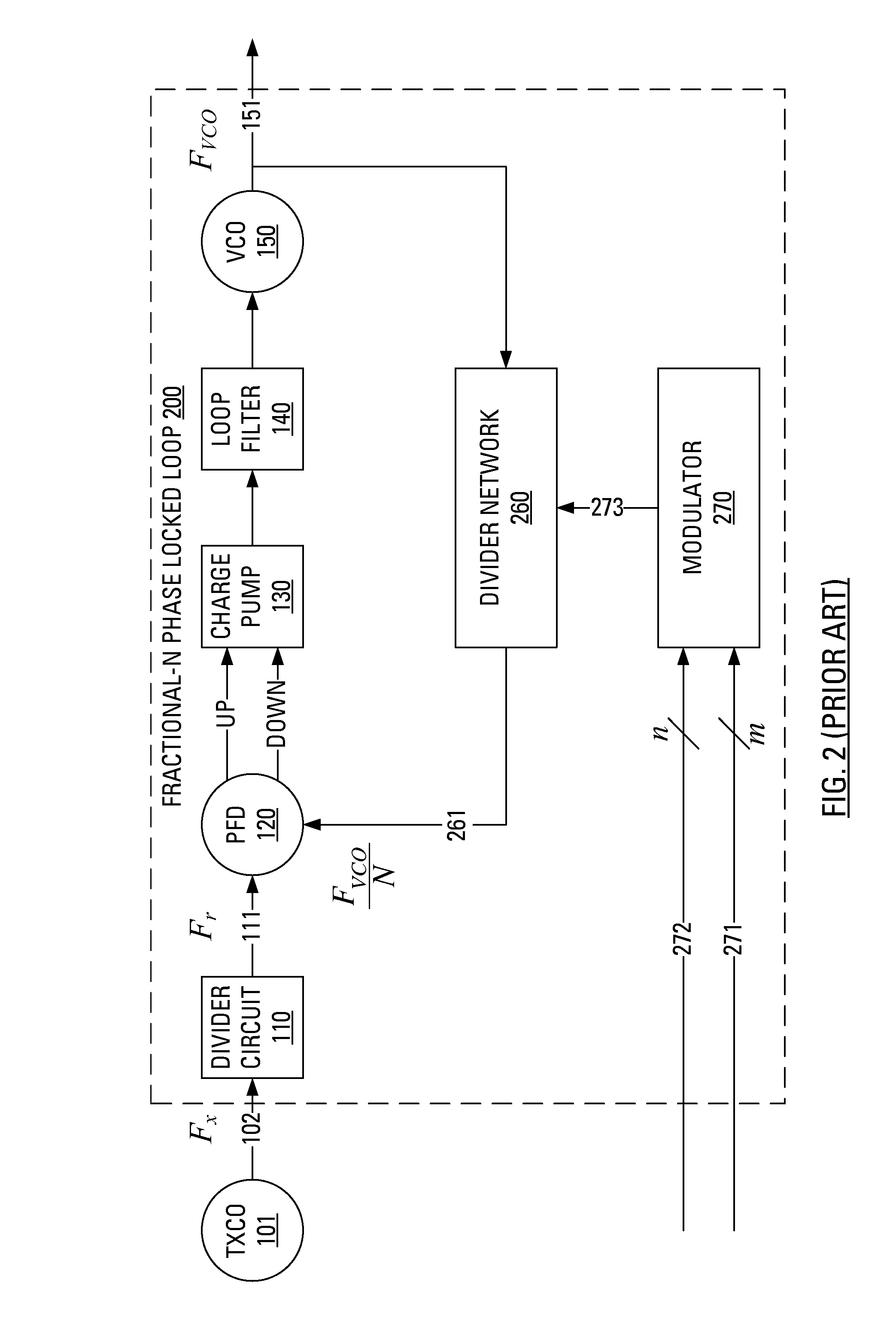
[0030]A conventional integer-N PLL 100 is shown in prior art FIG. 1. The conventional integer-N PLL 100 employs a phase frequency detector (PFD) 120 having, as inputs, a reference signal 111 (with a “reference” frequency Fr) and a feedback signal 161. The PFD 120 has, as outputs, phase control signals (UP / DOWN). The conventional integer-N PLL 100 also employs a VCO 150 and a divide by integer N circuit 160 (a divider network) that operates, on a signal 151 output from the VCO 150 with “output” frequency FVCO, to generate the feedback signal 161. Typically, a charge pump 130 and a loop filter 140 are interposed between the output of the PFD 120 and the input of the VCO 150.

[0031]In operation, the phase control signals (UP / DOWN) generated by the PFD 120 depend upon the phase and frequency differences between the reference signal 111 and the feedback signal 161. The phase control signals (UP / DOWN) generated by the PFD 120 are provided to the charge pump 130 and the resultant output of ...


PUM


Abstract

Correction of glitches output from a delta-sigma modulator is accomplished using an integer boundary crossing detector and a FIR filter. The detector monitors a portion of an input to the modulator. The detector recognizes a transition from an all 1's bit pattern to an all 0's bit pattern or vice versa as representative of potential for a glitch to be present on the output of the modulator. The detector responsively generates condition detection output. Receipt of such condition detection output triggers the generation of a correction signal by the filter. The correction signal is, at least substantially similar, in magnitude but opposite in sign from to the expected glitch at the output of the modulator. The correction signal is added to the output of the modulator to substantially eliminate the glitch.

Description

RELATED APPLICATIONS[0001]The present application claims priority from U.S. provisional Patent Application No. 60 / 912,310, filed Apr. 17, 2007, which is incorporated herein by reference in its entirety.BACKGROUND[0002]Wireless communications systems are not presently capable of directly processing and generating radio frequency (RF) signals. Accordingly, wireless communication system designs will continue to employ traditional RF engineering techniques of down-converting from RF to baseband, and / or techniques of down-converting from RF to intermediate frequency (IF) signals, for processing and up-converting the processed signals for transmission.[0003]In wireless transceivers, a wide range of frequencies may be used. In order to perform the down-conversion and / or up-conversion operations, stable and accurate frequency sources, such as crystal oscillators, are employed.[0004]Although there exist a variety of frequency synthesis techniques, the use of phase locked loops (PLLs) remains...

Claims


Application Information

Patent Timeline
Patent Type & Authority Applications(United States)
IPC IPC(8): H03C3/08
CPCH03C3/0925H03C3/0933
Inventor GALLOWAY, BRIAN JEFFREYHILLMAN, DANIEL
Owner CONVERSANT INTPROP MANAGEMENT INC
Why Eureka
Try Eureka