Multilayer-film reflective mirror, exposure apparatus, device manufacturing method, and manufacturing method of multilayer-film reflective mirror

a reflective mirror and multi-layer film technology, applied in the field of multi-layer film reflective mirrors, can solve the problems of increasing the machining workload and not getting the desired optical characteristic, and achieve the effect of favorable exposure of the substrate and suppressing the increase of the machining workload

Active Publication Date: 2008-10-23
NIKON CORP
View PDF15 Cites 51 Cited by
  • Summary
  • Abstract
  • Description
  • Claims
  • Application Information

AI Technical Summary

Benefits of technology

[0011]According to the second aspect exemplifying the present invention, a multilayer-film reflective mirror which can offer a desired optical characteristic is provided. Therefore, a substrate can be favorably exposed.
[0013]According to the third aspect exemplifying the present invention, a device can be manufactured by use of the exposure apparatus that can favorably expose a substrate.
[0015]According to the fourth aspect exemplifying the present invention, by heating at least a part of a multilayer film, a region comprising a first group with a first periodic length and a second group with a second periodic length different from the first periodic length is formed. Therefore, a multilayer-film reflective mirror which can offer a desired optical characteristic can be manufactured while suppressing increases in the machining workload.
[0016]According to the some aspects of the present invention, a multilayer-film reflective mirror can offer a desired optical characteristic. An exposure apparatus provided with the multilayer-film reflective mirror can favorably expose a substrate. Furthermore, a device with a desired performance can be manufactured by use of the exposure apparatus.

Problems solved by technology

When a surface of a multilayer film of a multilayer-film reflective mirror is machined to remove a part of a layer of the surface in order to adjust an optical characteristic of the multilayer-film reflective mirror, there is a possibility of increasing the machining workload.
Furthermore, when a surface of a multilayer film is machined to remove a part of a layer of the surface thereof, there is a possibility that a desired optical characteristic is not obtained due to a stepwise change in phase change amount between a machined region and an unmachined region, or the like.

Method used


Image

  • Multilayer-film reflective mirror, exposure apparatus, device manufacturing method, and manufacturing method of multilayer-film reflective mirror
  • Multilayer-film reflective mirror, exposure apparatus, device manufacturing method, and manufacturing method of multilayer-film reflective mirror
  • Multilayer-film reflective mirror, exposure apparatus, device manufacturing method, and manufacturing method of multilayer-film reflective mirror

Examples


first embodiment

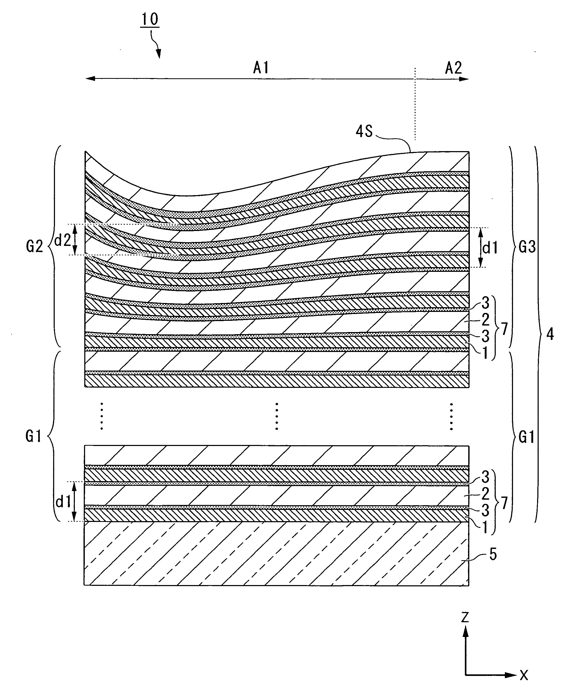
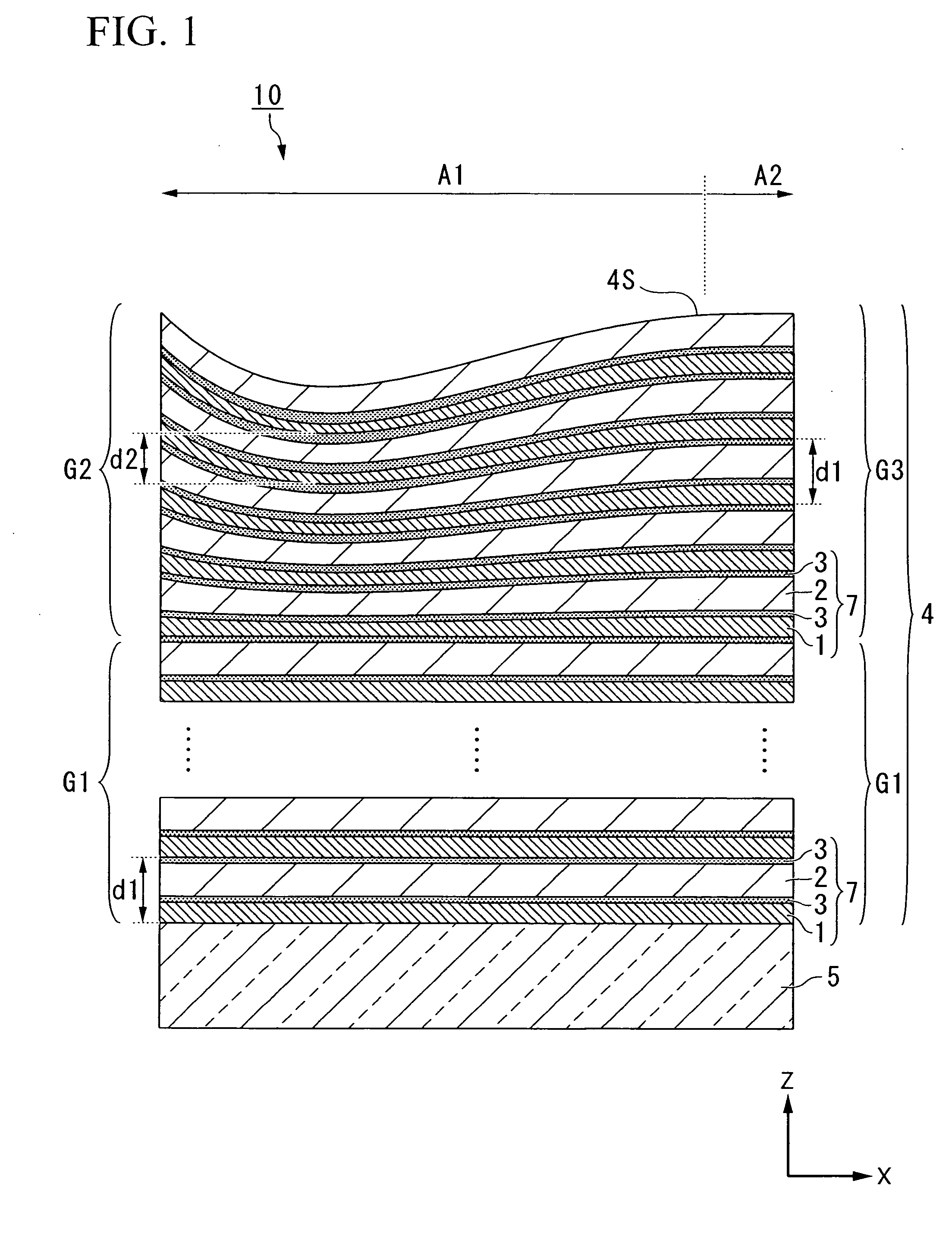
[0031]A first embodiment will be described. FIG. 1 is a schematic diagram showing one example of a multilayer-film reflective mirror 10 according to the first embodiment. In FIG. 1, the multilayer-film reflective mirror 10 comprises: a base 5; and a multilayer film 4 that comprises first layers 1 and second layers 2 alternately laminated on the base 5 and is capable of reflecting extreme ultraviolet light. The multilayer-film reflective mirror 10 further comprises, between the first layer 1 and the second layer 2, a diffusion layer 3 that is formed by diffusion of a material forming the first layer 1 and a material forming the second layer 2.

[0032]Extreme ultraviolet light is an electromagnetic wave in a soft X-ray region (extreme ultraviolet region) at a wavelength of for example approximately 5 to 50 nm, which is reflected by the multilayer film 4. In the following description, extreme ultraviolet light is appropriately referred to as EUV light.

[0033]The base 5 is formed of for ex...

second embodiment

[0081]Next is a description of a second embodiment. In the following description, components the same as or similar to those of the aforementioned embodiment are denoted by the same reference symbols, and descriptions thereof are simplified or omitted.

[0082]FIG. 6 is a schematic diagram showing a multilayer-film reflective mirror 10B according to the second embodiment. In the present embodiment, the multilayer-film reflective mirror 10B comprises a protective layer 6 arranged so as to cover a surface 4S of a multilayer film 4.

[0083]Similarly to the above embodiment, the multilayer film 4 has: a first region A1 that comprises a first layer group G1 with a first periodic length d1 and a second layer group G2 with a second periodic length d2; and a second region A2 that comprises a first layer group G1 at the first periodic length d1 and a third layer group G3 at the same periodic length as the first periodic length d1. The surface 4S of the multilayer film 4 is formed of a second laye...

third embodiment

[0103]Next is a description of a third embodiment. In the following description, components the same as or similar to those of the aforementioned embodiments are denoted by the same reference symbols, and descriptions thereof are simplified or omitted.

[0104]FIG. 10 is an exposure apparatus according to the third embodiment. The exposure apparatus EX in the present embodiment is an EUV exposure apparatus which uses EUV light as exposure light EL. The multilayer-film reflective mirror 10 (10B) described in the above first and second embodiments is used for an optical system of the EUV exposure apparatus EX according to the present embodiment.

[0105]In FIG. 10, the exposure apparatus EX comprises: a mask stage 11 capable of moving while holding a mask M; a substrate stage 12 capable of moving while holding a substrate P onto which exposure light EL is irradiated; an illumination optical system IL for illuminating the mask M held on the mask stage 11 with exposure light EL; a projection ...


PUM


Abstract

Multilayer-film reflective mirrors are disclosed. An exemplary such mirror has a base and a multilayer film formed on the base. The multilayer film includes multiple layer pairs. Each layer pair includes a respective first layer and a respective second layer, wherein the first and second layers are laminated together in an alternating manner. The multilayer film has first and second regions that reflect extreme ultraviolet light. A first group of layers is disposed in the first and second regions and has a first periodic length. A second group disposed in the first region has a second periodic length different from the first periodic length, and a third group disposed in the second region has a substantially same periodic length as the first periodic length.

Description

CROSS REFERENCE TO RELATED APPLICATION[0001]This application is a non-provisional application claiming priority to and the benefit of U.S. provisional application No. 60 / 907,935, filed Apr. 23, 2007, the entire contents of which are incorporated herein by reference.BACKGROUND[0002]1. Field of the Invention[0003]The present invention relates to a multilayer-film reflective mirror, an exposure apparatus, a device manufacturing method, and a manufacturing method of a multilayer-film reflective mirror.[0004]2. Description of Related Art[0005]In an exposure apparatus for use in a photolithography process, there is proposed an EUV exposure apparatus as disclosed for example in U.S. Patent Application, Publication No. 2005 / 157384, in which Extreme Ultra-Violet (EUV) light is used as exposure light. In an optical system of an EUV exposure apparatus, a multilayer-film reflective mirror is used.[0006]When a surface of a multilayer film of a multilayer-film reflective mirror is machined to rem...

Claims


Application Information

Patent Timeline
Patent Type & Authority Applications(United States)
IPC IPC(8): G02B5/26G02B1/10B05D5/06
CPCB82Y10/00G02B5/0891G03F1/24G21K2201/067G21K1/062G21K2201/064G03F7/70958
Inventor SHIRAISHI, MASAYUKI
Owner NIKON CORP
Why Eureka
Try Eureka