Sampling and Assay Device

Active Publication Date: 2008-10-23
ORION DIAGNOSTICA
View PDF17 Cites 68 Cited by
  • Summary
  • Abstract
  • Description
  • Claims
  • Application Information

AI Technical Summary

Benefits of technology

[0018]Such a device enables for instance the preparation of the final reagents to be used in an assay. Two or more reagents are partitioned in chambers to avoid their mutual reaction before introduction of the sample to be analysed. In order to accomplish a simultaneous contact between the sample and the two or more available reagents the reservoir members are ruptured simultaneously. In some circumstances it is of importance to have the option to bring two or more reagents together simultaneously just prior to performance of the assay. This is particularly important with reagents which show high or higher stability before combination than after combination. The location of reagents in separate chambers until use provide an excellent stability of the reagents. Consequently, the present invention enables introduction of a high quality reagent on a beforehand defined exact moment. Moreover, the sample collecting and test device of the present invention may be stored for long periods of time, possibly in conditions which usually are not optimal for storage. Thus, the device is suitable for simple and reliable sampling and determination of analyte in the sample, as well as storage prior to use.
[0020]This arrangement simplifies and further assists the combination of the reagents enclosed in the test device, and obviates the use of a sample element for breaking the partitions.
[0022]The partitions may be of any suitable form to prevent leakage of reagent between the chambers. For example, they may be a relatively thin seal or membrane, such as an aluminium foil, formed of a different material from the chamber portions or may be a relatively thick member formed of the same material as the chamber portions. The partitions in the device may be of different configuration, structure or material.
[0023]The invention enables a compact configuration of various analyses through its partitioned reagent chamber structure and a rupture arrangement which is simple to use. In addition, the rupture arrangement is not dependent on the sampling element, thus making the device more applicable to various assay and sampling methods, and the means by which the sample is introduced into the device. The device is applicable to various types of sample and reagent since the sampling element is not required in the process of breaking the partitions.
[0030]Advantageously, the sampling and assay device further comprises a barrier element extending across the chamber of the one of the chamber portions which has the partition fixed thereto to prevent passage of the ruptured partition. This prevents the ruptured partition, which may become detached in part or in full from passing into the adjacent chamber where it might prevent proper mixing of the reagents or prevent proper inspection of the analyte. The barrier element is sufficiently open to allow passage of any desired reagent or sample into the reaction reservoir.
[0036]Such a system allows straightforward production of a variety of different sampling and assay devices having different reagents by assembly of the chamber portions.

Problems solved by technology

Moreover, the sample collecting and test device of the present invention may be stored for long periods of time, possibly in conditions which usually are not optimal for storage.

Method used


Image

  • Sampling and Assay Device
  • Sampling and Assay Device
  • Sampling and Assay Device

Examples


example 1

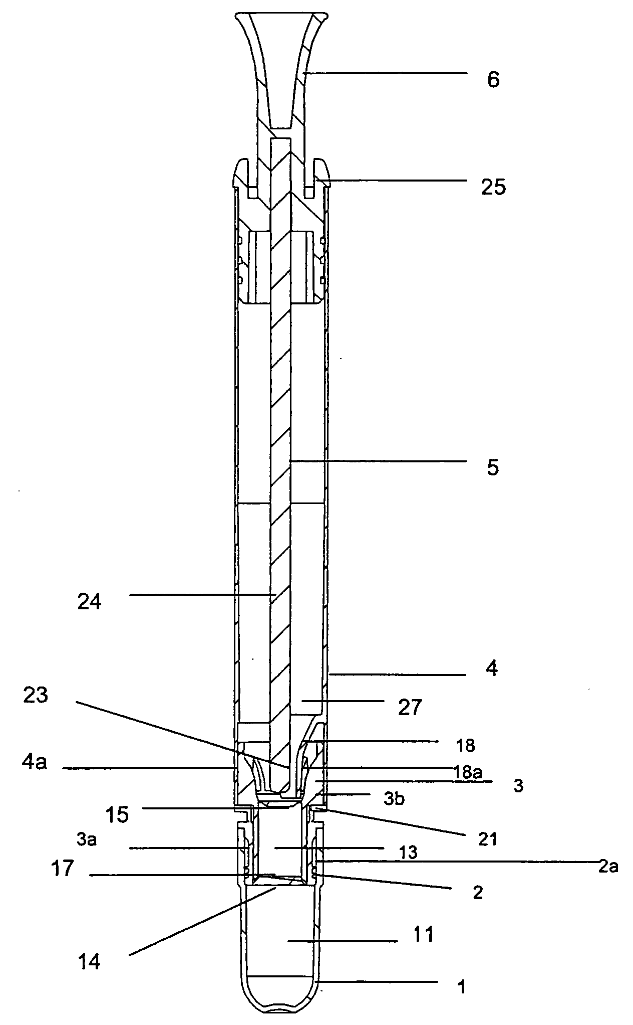
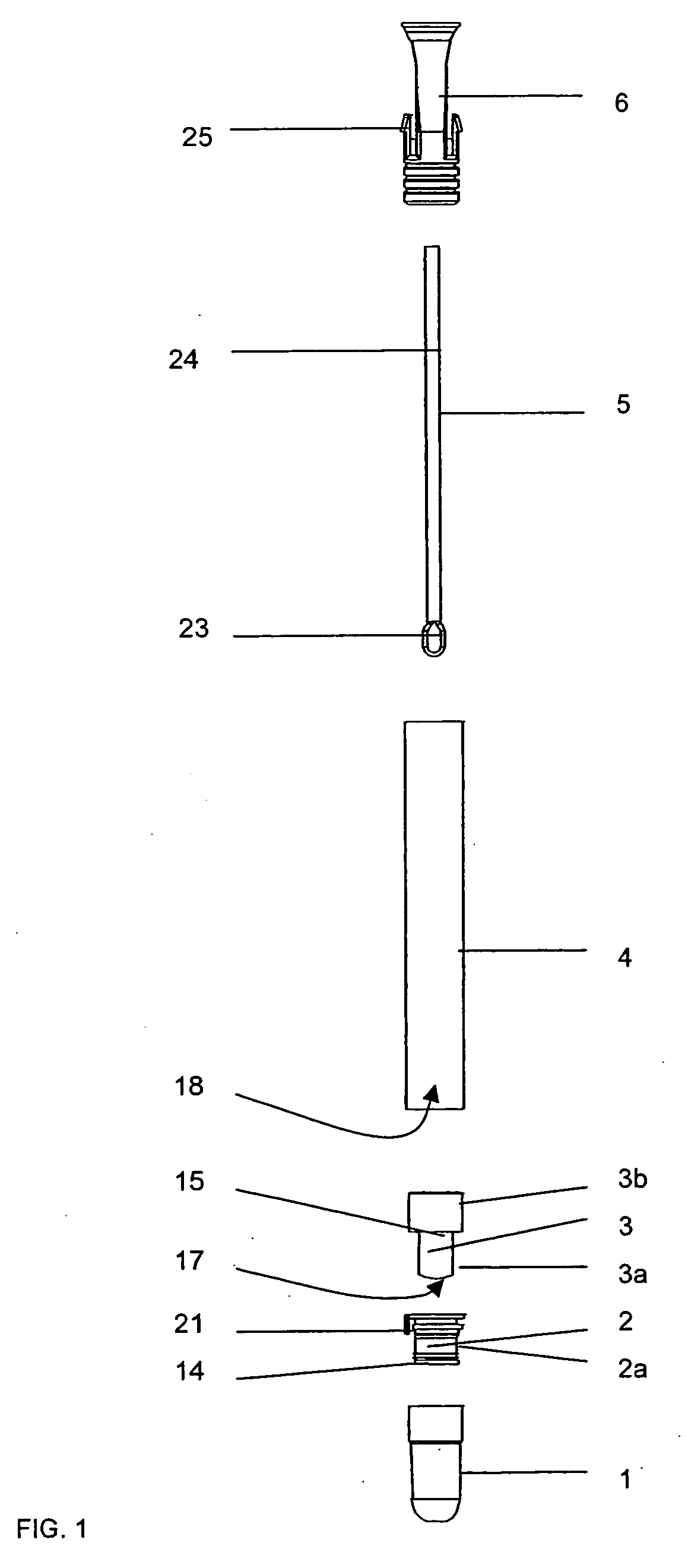
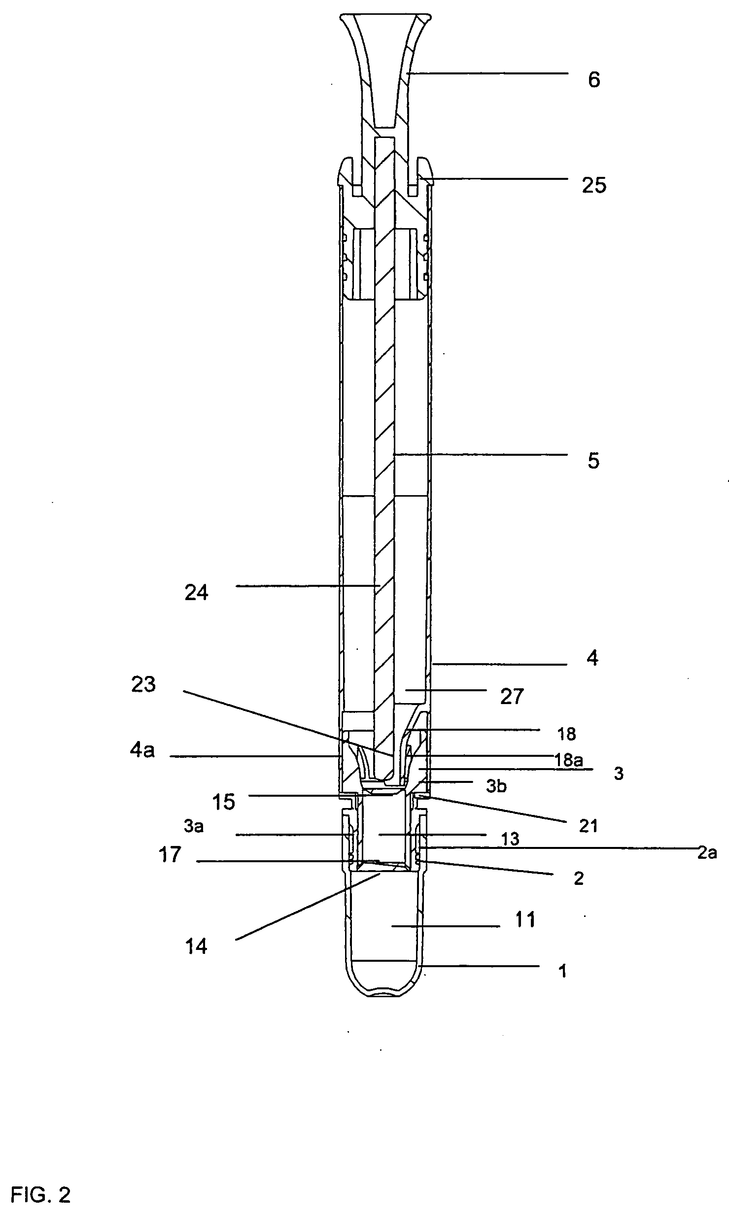
[0085]The first device of FIGS. 1 and 2 is suitable for detection of reducing agents, including proteins and reducing sugars e.g. glucose, fructose, lactose and maltose. The sample, indicative of surface cleanliness / dirtiness, is taken by wiping a surface with a sampling element 5 initially placed inside the tubular body 4 of the device. The sampling element 5 is inserted back inside the tubular body 4, and the tear strip 21 between the sealing cap 2 and the reagent chamber portion 3 is removed. There is copper reagent (4% aqueous CuSO4.5H2O) in the chamber 13 defined by the reagent chamber portion 3, and organic acid reagent (4% organic acid, sodium carbonate and bicarbonate, and sodium tartrate in 0.1 M NaOH) in the chamber 11 defined by the reaction chamber portion 1. These reagents are combined by relative movement of the reaction chamber portion 1 and the tubular body 4. By this movement the rupture member 17 of the reagent chamber portion 3 and the rupture element 18a of the t...

example 2

[0086]The second device of FIGS. 3 and 4 is suitable for Group A Streptococci (Streptococcus pyogenes) detection and measurement by Quik Read photometric reader (Orion Diagnostica, Finland). The sample is taken by wiping the pharyngeal cavity with a sampling element 5 initially placed inside the tubular body 4 of the device. The sampling element 5 is inserted back inside the tubular body 4, and the tear strip 22 between the additional sealing cap 7 and the reagent chamber portion 3 is removed. There is a first extraction reagent (0.02% phenol red in 3 M NaNO2) in the chamber 13 defined by the reagent chamber portion 3 and the tubular body 4 and a second extraction reagent (0.005 M EDTA in 1 M acetic acid) in the chamber 12 defined by the additional chamber portion 8. These reagents are combined relative movement of the additional chamber portion 8. By this movement the rupture member 17 of the reagent chamber portion 3 and the rupture member 18 of the tubular body 4 rupture the part...


PUM

PropertyMeasurementUnit
pHaaaaaaaaaa
relative movementaaaaaaaaaa
transparentaaaaaaaaaa

Abstract

A sampling and assay device comprises at least three chamber portions (1, 3, 4) connected together in a row. Each chamber portion (1, 3, 4) defines a chamber (11, 13, 27) and adjacent chambers (11, 13, 27) along the row are separated by respective partitions (14, 15). One end chamber (4) is capable of receiving a sample either on a swab or as a liquid. The other chambers (11, 13) contain reagent for performing the assay. Adjacent chamber portions (1, 3, 4) along the row are relatively movable towards each another. In respect of each pair of adjacent chamber portions (1, 3), one of the adjacent chamber portions (1) has the respective partition (14) fixed thereto and the other of the adjacent chamber portions (3) has a rupture member (17) arranged to rupture the respective partition (14) on relative movement of the adjacent chamber portions (1, 3). As a result, the sampling and assay device is capable of rupturing each partition (14, 15) simultaneously on relative movement of the chamber portions (1, 4) at the ends of the row towards each other. Also, each pair of adjacent chamber portions (1, 3) have respective connection portions (2a, 3a) mated together, the connection portions (2a, 3a) being designed to allow further chamber portions identical to an intermediate chamber portion to be connected into said row.

Description

TECHNICAL FIELD OF THE INVENTION[0001]The present invention relates to a device for preparation of sample and assay for determination or detection of an analyte, for example by a semi-quantitative or by quantitative inspection apparatus or by semi-quantitative visual inspection of the result and for taking a sample and transportation thereof.BACKGROUND OF THE INVENTION[0002]For on site testing it is essential to minimise the amount of reagent handling. This can be achieved by using a compact sampling and assay device that contains all the necessary reagents needed for performance of the assay. In many assays, two or more reagents may be used that are combined just prior to, during or after sampling. To fulfil these needs compartmentalised structures with separate reagent reservoirs have been introduced. Several sample preparation and assay devices have been developed for various types of analysis that are aimed for facilitated sampling in both laboratory and non-laboratory environme...

Claims


Application Information

Patent Timeline
Patent Type & Authority Applications(United States)
IPC IPC(8): B01J19/00B01L3/00B01L3/14B65D81/32C12M1/30G01N1/02
CPCB01L3/5029B01L3/5082B01L2200/025B01L2200/028B01L2300/042B01L2300/0672B01L2300/0832B01L2400/0683B65D81/3211G01N2001/028
Inventor ROSMAN, ESAKYLMA, ANNA KAISAHAIVA, VELI-MIESGRANBERG, CHRISTER
Owner ORION DIAGNOSTICA
Why Eureka
Try Eureka