Mri Compatible Implant Comprising Electrically Conductively Closed Loops

a technology of electrically conductive closed loops and compatible implants, which is applied in the field of implants, can solve the problems of little information derived from the portion of the image corresponding to the stent lumen, the stent lumen is not clearly visible in the mri image, and the mechanical strength of the stent is affected, so as to achieve the effect of mitigating the tendency of the implan

Inactive Publication Date: 2008-10-23
ANGIOMED GMBH & CO MEDIZINTECHNIK KG
View PDF43 Cites 34 Cited by
  • Summary
  • Abstract
  • Description
  • Claims
  • Application Information

AI Technical Summary

Benefits of technology

[0019]According to the present invention there is provided an implant, as defined above, and characterised by first and second current pathways that are arranged in any one closed loop such that, in any particular electromagnetic field, the direction of the eddy current that would be induced in the second current pathway is the reverse of the direction of the eddy current that would be induced in the first current pathway, so as to mitigate the tendency of the implant to function in said magnetic field as a Faraday cage.
[0020]The insight which the inventors have brought to the problem is that an arrangement of conductive current pathways in a loop which is liable to give rise to eddy currents is not a disadvantage, provided that there is, at the same time, another part of the same electrically-conductive closed loop that is liable to induce eddy currents of equal strength, but in the opposing direction. In this way, the aggregate flow of current in the closed loop is zero (or near zero), and so the Faraday screening effect preventing the interior lumen of the implant from being imaged by MRI is at least mitigated, or even eliminated.
[0025]Let us revert to the simplest case of two parallel wires of electrically conductive material. If an AC current flows in one of these wires then, by a process of induction, eddy currents will be caused to flow in the second wire but in the opposite direction to that in the first wire. Extending this principle, when a number of wires run close to and parallel to each other, then eddy currents are caused to flow in neighbouring wires due to the current in any particular wire. The net effect of all these additional eddy currents is that the effective resistance of each wire is increased. This effect is often noted in transformer and inductor winding and it is commonly termed the “proximity effect”. This effect can be used to deliberately increase the resistance of all the loops in the implant, by making all the loops as convoluted as possible and by running the loops as close to each other as possible, so that the proximity effect is maximised. This has the effect of decreasing the currents that can flow in that implant, so that the visibility of the implant lumen is improved in the MRI image.
[0031]The flexibility of the stent thus formed varies with the number of links or bridges that connect each of the stenting rings to the axially adjacent stenting ring next to it along the length of the stent. Thus, the stent exhibits closed electrically conductive loops around the lumen of the stent, and other closed loops that extend along the lumen within the annular envelope of the stent. One can appreciate that, when adjacent stenting rings are connected by only one link at only one point of the circumference of the metal tube, there is considerable freedom for relative bending movement of one stenting ring relative to the next adjacent stenting ring. Indeed, in the ultimate, one can make entirely separate stenting rings and sandwich them between two layers of tubular graft material so that the flexibility of the resulting stent graft, between two adjacent stenting rings, is limited only by the stiffness of the graft material, and not by the material of the stenting rings. However, for an uncovered stent, it is typical to provide a number of links between adjacent stenting rings that is less than eight per circumference, and often four per circumference.
[0047]A major advantage of both the “figure of eight” and the “wrapped” or “winding” loops is that the cancelling effect is independent of the orientation of the stent with respect to the direction of the B1-field. Thus, a stent which embodies the concept does not form a Faraday cage whatever its orientation with respect to the B1-field. Hence, the detrimental screening effects due to the Faraday cage are at least mitigated, if not eliminated. This renders such a configured stent particularly attractive, because the lumen or the interior volume of the stent can be imaged using an MRI imaging machine irrespective of the orientation of the stent with respect to the direction of the B1-field.
[0048]For structural integrity, there can be connections between portions within each winding loop, and other connections between adjacent winding loops, and all of these connections should include conductivity breaks. There will be a premium on reducing the number of electrically-conductive links. The ability to install conductivity breaks in these links will give the designer more freedom to manipulate the mechanical properties of the implant thus formed.

Problems solved by technology

However, when one takes an image of a field of view that includes a conventional metal stent, little information can be derived from the portion of the image corresponding to the stent lumen.
The metal stent functions as a Faraday cage, to shield the lumen from the B1-field, with the result that the lumen of the stent is not rendered clearly visible in an MRI image.
However, there are disadvantages associated with each of these prior proposals.
However, this has consequences for the mechanical strength of the stent, and for the steps involved in its manufacture.
In bare stents, however, separating the stenting rings has consequences for the mechanical integrity of the stent, whether it will survive the rigours of assembly and delivery, and how feasible it is to manufacture such a stent.

Method used


Image

  • Mri Compatible Implant Comprising Electrically Conductively Closed Loops
  • Mri Compatible Implant Comprising Electrically Conductively Closed Loops
  • Mri Compatible Implant Comprising Electrically Conductively Closed Loops

Examples


Embodiment Construction

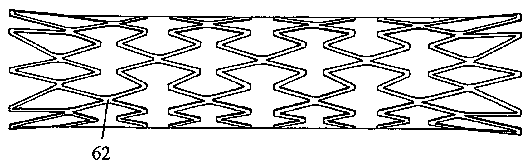
[0070]Typically, a stent is made from metal wire, or a tubular matrix of metallic struts can be formed from seamless tubular material, or from flat sheet material rolled up. Although the following description only refers to transluminally-delivered, expansible stents, the principle of the present invention may be applied to medical implants in general other than transluminal stents, such as implants installed in a bodily lumen by open surgery, filters such as vena cava filters, fluid-flow measuring devices, valves such as heart valves or venous valves, etc.

[0071]To prevent eddy currents from flowing, one alternative has been to eliminate conducting links between adjacent stenting rings that form the stent. This, however, physically weakens the stent so that it may fail to operate properly, e.g. it may not deploy correctly and once deployed it may not be strong enough to withstand the arterial pressures. Connecting the stenting rings by means of insulating joints brings extra manufac...


PUM


Abstract

The present invention relates to an implant 100 which comprises a plurality of electrically-conductive closed loops (300A, 300B, 300C, 300D; 120A, 120B, 120C, 120D each constituted from a plurality of loop portions such as struts (400, 500). The loops together form apertured walls of a cage with an interior volume, and the portions in any one said loop providing electrically-conductive pathways within which eddy currents are liable to be induced when the implant is subjected to an time-dependent external magnetic field, with each said loop comprising at least first and second said pathways. The implant is characterized in that the first and second pathways are arranged such that, in any particular magnetic field, the direction of the eddy current that would be induced in the second pathway is the reverse of the direction of the eddy current that would be induced in the first pathway, so as to mitigate the tendency of the implant to function in said magnetic field as a Faraday cage.

Description

FIELD OF THE INVENTION[0001]This invention relates to an implant having a plurality of electrically-conductive closed loops constituted from a plurality of portions that may be struts, the loops together forming apertured walls of a cage with an interior volume, the portions in any one said loop providing electrically-conductive pathways within which eddy currents are liable to be induced when the implant is subjected to a time-dependent external magnetic field, with each said loop having at least first and second said current pathways.[0002]The archetypal implant considered here is a metal stent to be delivered in a radially compact configuration, transluminally, by a catheter, and then expanded into a radially larger deployed configuration, at a stenting site within a bodily lumen. However, the range of implants is steadily growing and the present inventors contemplate use of the invention in a wide range of implants other than stents. One particular example is a filter, such as a...

Claims


Application Information

Patent Timeline
Patent Type & Authority Applications(United States)
IPC IPC(8): A61F2/86A61F2/00A61F2/88A61F2/91A61F2/915
CPCA61F2/88A61F2/91A61F2/915A61F2002/91508A61F2002/91516A61F2002/91525A61F2230/0054A61F2002/91558A61F2002/91591A61F2250/0045A61F2220/0033A61F2220/005A61F2220/0058A61F2002/91541
Inventor LAITENBERGER, PETER GEORGSCOTT, VALERIE ANNEWEBBER, DOMINIC GEORGEPOOLEY, DAVID MARTINJAMES, DAVID ALUNBLANK, THIEMO ARNIM
Owner ANGIOMED GMBH & CO MEDIZINTECHNIK KG
Why Eureka
Try Eureka