
Metal core welding wire pulsed welding system and method

a metal core welding and pulsed welding technology, applied in the field of pulsed gas metal arc welding systems, can solve the problems of adding more heat to the workpiece, consuming more power than necessary, and weld puddles which may be too fluid,

Inactive Publication Date: 2008-10-30
ILLINOIS TOOL WORKS INC
View PDF16 Cites 49 Cited by
  • Summary
  • Abstract
  • Description
  • Claims
  • Application Information

AI Technical Summary

Benefits of technology

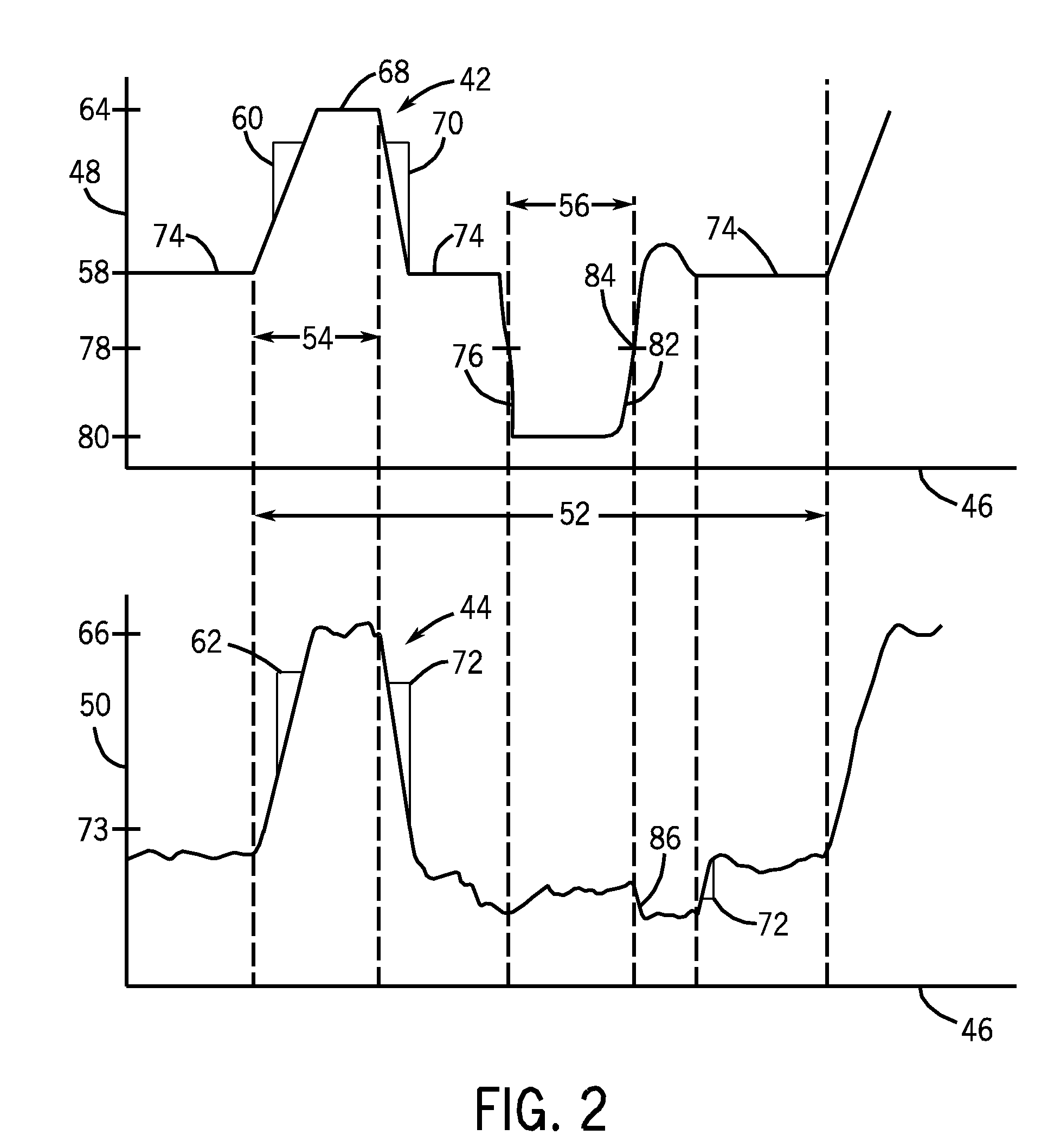
The invention provides a better way to weld using a special waveform that is suitable for metal core welding wires and reduces damage to the wire core. The waveform has a very short peak pulse of voltage, current, power, or energy, with a duration of less than 0.2 milliseconds. The ratio of the peak pulse duration to the overall duration of the waveform is less than 1%. This special waveform is particularly useful for metal core welding wires and helps to improve the quality of the weld.

Problems solved by technology

Maintaining a high constant voltage adds more heat to the work piece and consumes more power than necessary.
The additional heat results in a weld puddle which may be too fluid for some applications, such as overhead or vertical welding.
Excessive heat may also cause thinner work pieces to warp and distort.
Though GMAW-P represents an improvement over typical GMAW, some problems persist.
The rapid transfer may cause the molten ball of electrode material or the weld puddle to spatter.
The high power of the peak phase may also heat the molten ball of electrode material beyond its boiling point, resulting in “outgassing” and microspatter caused by electrode vaporization.
While such a restrike phase usually succeeds, at the moment the arc restrikes the current and voltage may be very high.
The high energy of the arc may cause the weld puddle to spatter and generate excessive heat.
While some software-controlled GMAW-P systems may take implement schemes to predict clearing of short-circuit conditions, such systems may be more expensive or unwieldy than more common GMAW-P systems.
In addition to the foregoing issues with gas shielded welding applications, waveforms similar to those used in MIG welding are sometimes used with metal core welding wires.
Conventional pulsed waveforms have not been widely used in such applications, however, particularly due to the higher levels of heating that may adversely affect the core of the wires.

Method used


Image

  • Metal core welding wire pulsed welding system and method
  • Metal core welding wire pulsed welding system and method
  • Metal core welding wire pulsed welding system and method

Examples


Embodiment Construction

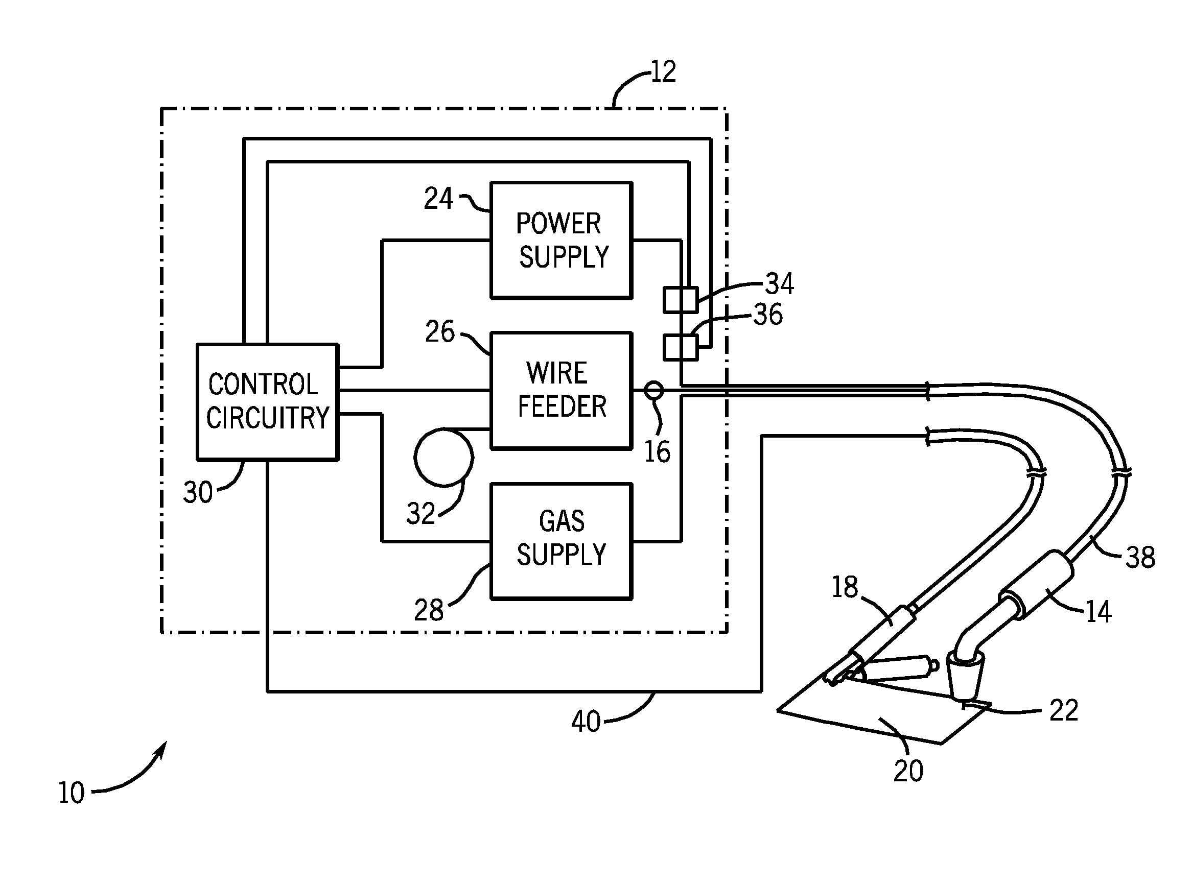
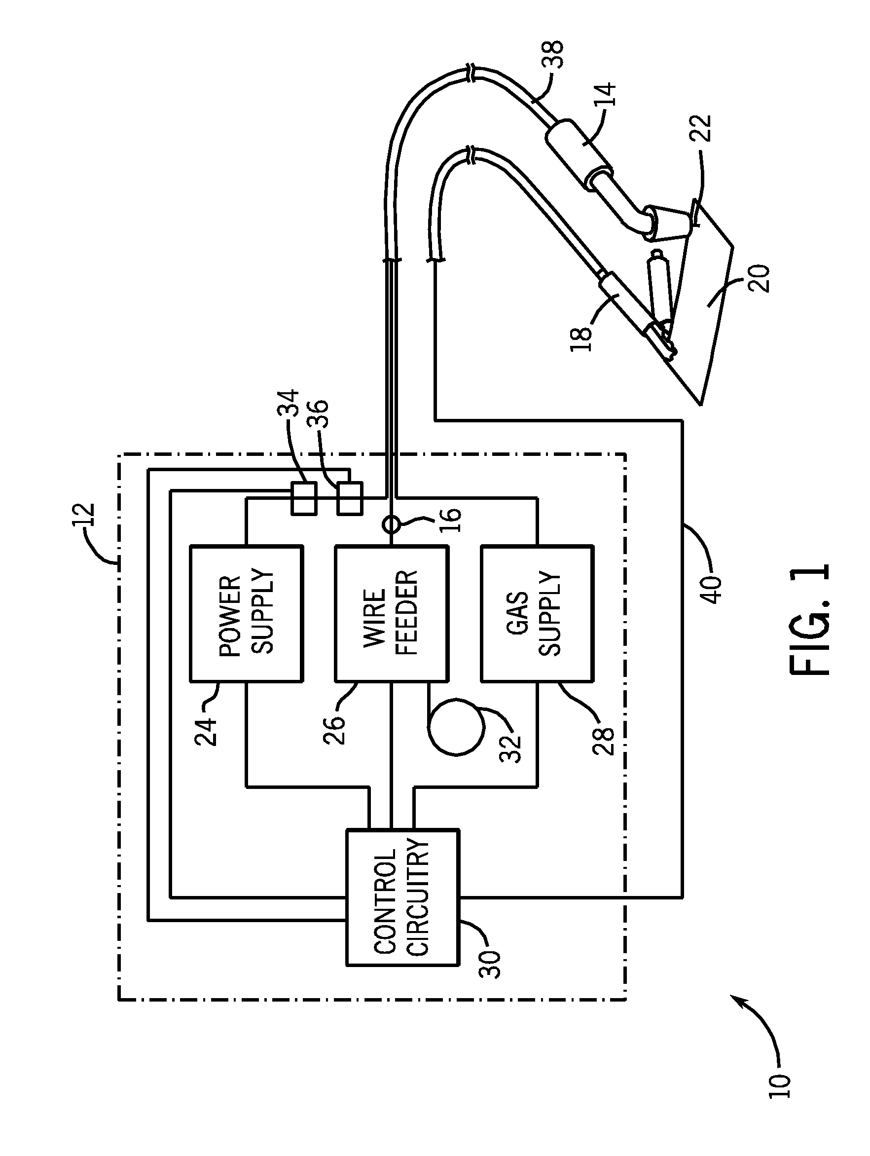
[0020]FIG. 1 illustrates an exemplary welding system 10 which is configured to utilize the present technique. Prior to continuing, however, it is worth noting that the following discussion merely relates to exemplary embodiments of the present technique. As such, the appended claims should not be viewed as limited to those embodiments described herein.

[0021]The exemplary welding system 10 includes a base unit 12 operably coupled with a welding torch 14. Placement of the welding torch 14 proximate to work piece 20 allows electrical current, supplied by power supply 24, to form an arc 22 from electrode 16 to the work piece 20. The arc 22 completes an electrical circuit from power supply 24 to electrode 16, to the work piece 20, then back to ground via ground clamp 18 and ground cable 40, which is operably coupled to power supply 24 through control circuitry 30. The heat produced by arc 22 causes the electrode 16 and / or work piece 20 to transition to a molten state, facilitating the we...


PUM

PropertyMeasurementUnit
peak voltageaaaaaaaaaa
peak currentaaaaaaaaaa

Abstract

Provided is a welding system and method for controlling a welding system with an improved pulsed waveform suitable for use with metal core welding wires. The waveform includes peak pulses (of voltage, current, power, energy or a combination thereof) that aid in transfer of molten metal from the wire to the weld pool. The pulse duration is sufficiently short to avoid damage to the metal core welding wire. The waveform enables welding of thin metals and reduces spatter.

Description

CROSS REFERENCE TO RELATED APPLICATIONS[0001]This application is a Non-Provisional Patent Application of U.S. Provisional Patent Application No. 61 / 066,138, entitled “Welding System and Method with Improved Waveform”, filed Apr. 30, 2007, which is herein incorporated by reference.BACKGROUND[0002]The invention relates generally to the field of welding systems, and particularly to pulsed gas metal arc welding systems (GMAW-P), also known as pulsed metal inert gas (pulsed MIG) welding systems.[0003]Arc welding systems generally comprise a power supply that applies electrical current to an electrode so as to pass an arc between the electrode and a work piece, thereby heating the electrode and work piece to create a weld. In many systems, such as gas metal arc welding systems (GMAW), the electrode consists of a wire which is advanced through a welding torch. As the electrode is heated by the arc, the electrode melts and is joined to molten metal of the work piece to form the weld. By con...

Claims


Application Information

Patent Timeline
Patent Type & Authority Applications(United States)
IPC IPC(8): B23K9/09B23K31/02
CPCB23K9/092B23K9/173
Inventor WHITE, GALEN JON
Owner ILLINOIS TOOL WORKS INC
Learn More