Planar Antenna for Mobile Satellite Applications

Active Publication Date: 2008-10-30
VIASAT INC
View PDF7 Cites 11 Cited by
  • Summary
  • Abstract
  • Description
  • Claims
  • Application Information

AI Technical Summary

Benefits of technology

[0014]The main objects of the present invention are to overcome afore cited drawbacks by providing an antenna assembly with low-profile which can be arranged very close or even in contact to any kind of mobile support and which has a homogenous conical radiation pattern with a satisfactory efficiency.
[0015]In order to achieve the above mentioned objects, the present invention concerns an antenna assembly such as a microstrip patch antenna (1) for mobile satellite communications that includes a first electrically conducting ground plane (4) having at least one opening (7; 10), at least one patch radiating element (2), at least one first dielectric layer (L2; L21-L22; L21-L23; L21-L25) disposed between the first electrically conducting ground plane and the patch radiating element and more particularly between the at least one opening and the patch radiating element, at least one feed line (6) for providing signal energy in a contactless manner to or from the patch radiating element through the opening and a second dielectric layer (L3) disposed between the feed line and the first electrically conducting ground plane wherein the antenna further comprises a second ground plane (8) and a third dielectric layer (L4) disposed between the second ground plane and the feed line. Accordingly, a more homogenous conical radiation pattern is obtained with the feed line that provides signal energy in a contact less manner to or from the patch radiating element through the opening. Nevertheless, contact less coupling impedes use of a metal pedestal connecting with the first electrically ground plane. Therefore, it is further provided with the arrangement of an additional foam or air layer together with a second ground plane which strongly reduces influences due to the vehicle support on which the antenna assembly is embedded and also allows reducing the minimum required distance between the vehicle and the antenna assembly.
[0016]Others advantageous features are considered in the other embodiments described herein and as recited in the claims. For instance, the use of specific dielectric layers allows an optimized radiation at low elevation angles and further reduces the size of the antenna. Further by using a feed line slot coupled to the patch radiating element, the antenna bandwidth is increased in comparison with excitation by feeding post according to the prior art solution. Furthermore, by using a particular slot disposition arrangement the circular polarization is particularly efficient.
[0018]In order to achieve this other object, the present invention also concerns a multi-system antenna assembly such as a multi-system antenna (21) for mobile communications that includes a first electrically conducting ground plane having at least first (27) and second (36, 37) openings; an annular patch radiating element (22) and a circular patch radiating element (33) concentrically arranged and coplanar with respect to the annular patch radiating element; at least one first dielectric layer disposed between the electrically conducting ground plane and the annular and circular patch radiating elements and more particularly between the first and second openings and the annular and circular patch radiating elements; at least first (26) and second (38) feed lines for providing signal energy in a contactless manner to or from the annular and circular patch radiating elements respectively through the first and second openings; and a second dielectric layer disposed between the first and second feed lines and the electrically conducting ground plane. The idea consists in particular to use the space left by the central part and / or the external periphery of the ring to integrate additional elements and hence access different systems without any increase in size and production cost.

Problems solved by technology

However, US Patent Application No. 2003 / 0210193 presents some drawbacks.
Therefore, the resulting antenna is less efficient.

Method used


Image

  • Planar Antenna for Mobile Satellite Applications
  • Planar Antenna for Mobile Satellite Applications
  • Planar Antenna for Mobile Satellite Applications

Examples


first embodiment

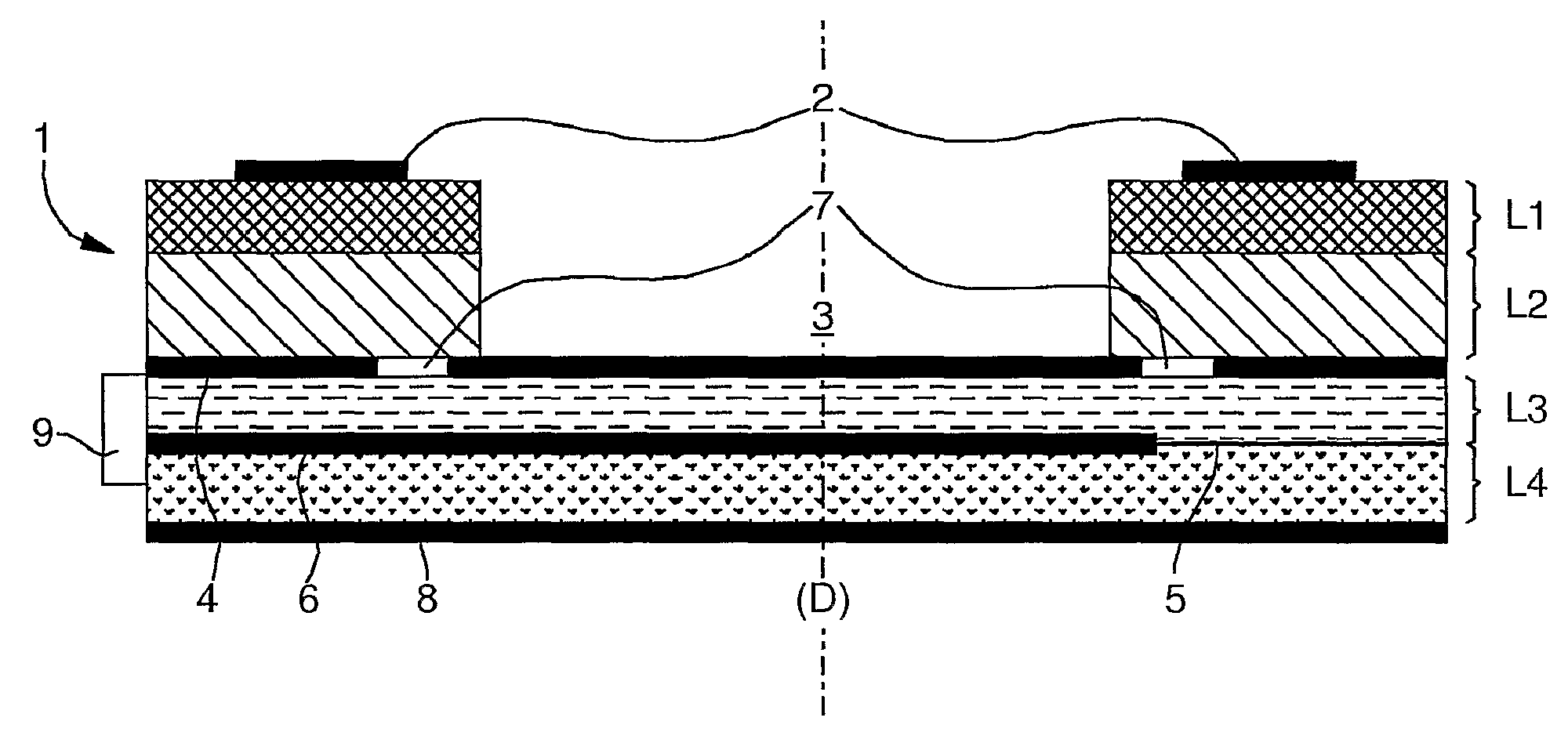
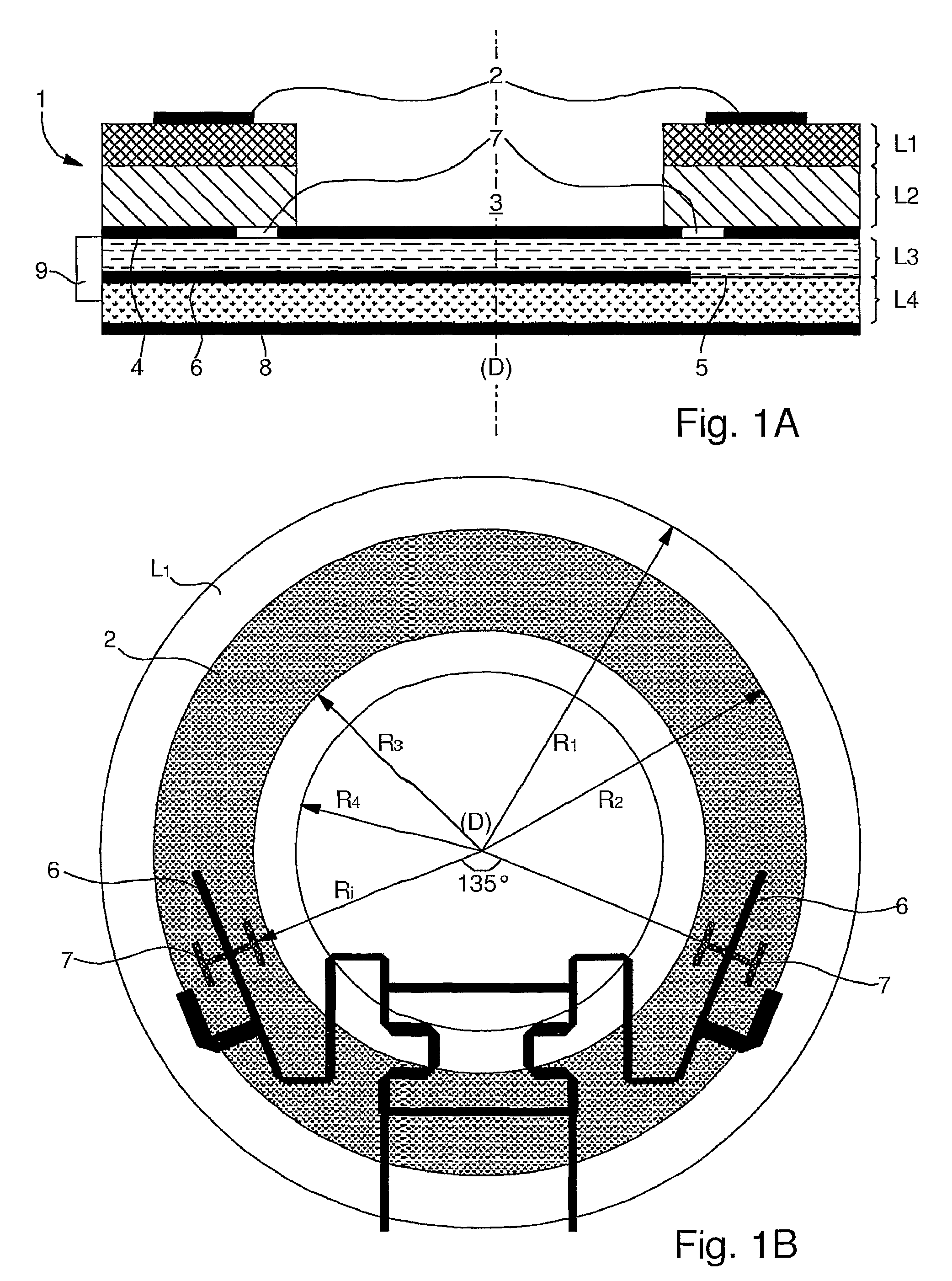
[0035]FIG. 1A is a cross section view of a simple antenna assembly according to the present invention. In terms of structure, antenna assembly 1 preferably occupies a thin disk-shaped or cylindrical volume having a central axis (D) and a height which can be divided into successive layers each being circular or ring-shaped.

[0036]Departing from the top of FIG. 1A and going downwards, antenna assembly 1 comprises an annular patch radiating element 2, preferably printed or etched on an annular epoxy film forming a first layer L1 which secures patch radiating element 2 to the whole antenna assembly. Annular epoxy film L1 is glued on a first dielectric substrate layer L2 formed by a plastic material. Nevertheless, annular epoxy film L1 can be omitted and then patch radiating element 2 is directly glued on plastic layer L2. According to the represented embodiment on FIG. 1A, plastic layer L2 is ring-shaped, a disk-shaped void 3 being let in the middle. However as it will be described herei...

second embodiment

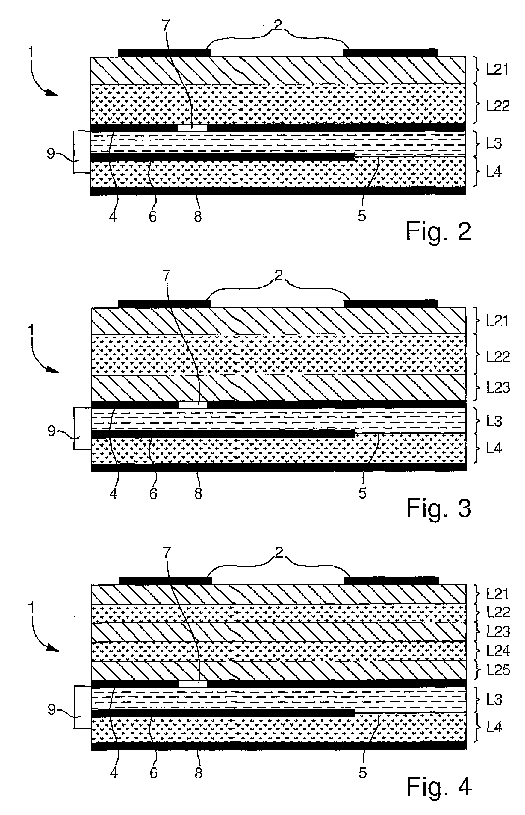
[0050]FIG. 2 is a cross section view of a simple antenna assembly according to a first variant of the present invention. All common elements with FIG. 1A will not be described in detail again.

[0051]The main difference between the previously described first embodiment and the second one relies on the dielectric substrate disposed between annular patch radiating element 2 and electrically conducting ground plane 4. In fact in the second embodiment, it is provided with a dielectric substrate based on sandwiched dielectric layers L21 and L22 composed of materials with different characteristics. The ad-hoc composition of dielectric layers L21 and L22 with different permittivity and thickness allows to synthesize the permittivity of the dielectric substrate between annular patch 2 and first ground plane 4, and therefore to optimise the size of the antenna and its performances.

[0052]Previous studies have shown that the use of high permitivitty substrates can be used not only to reduce the ...

third embodiment

[0068]Given below is an array with the dimensions of the different layers (L1, L21-L23 and L3-L4) according to a preferred example of the above described Also given below are the dielectric constants (Dc), also called dielectric permittivity, of the different layers.

LayerMaterialThickness (mm)Dc L1Epoxy (optional layer)0.54.4L21Plastic only or0.8 to 52.3Plastic + EpoxyL22Epoxy + Foam 0.1 to 2-34.4or Epoxy onlyL23Plastic0.8 to 52.3 L3PTFE0.53 L4Foam (or air)1 à 51.05

[0069]It is to be noted that electromagnetic-coupling is less influenced than slot-coupling by the support of the antenna (e.g. the car-top) and therefore the height of layer L4 could be further reduced.

[0070]FIG. 7 is a partial top view of a first multi-system antenna assembly 21 according to any of the preceding embodiments of the present invention. In this multi-system antenna, it is provided with antennas for at least two applications and preferably more than two. A very interesting feature is the overall size of suc...


PUM


Abstract

The invention relates to a microstrip patch antenna (1) for mobile satellite communications comprising a first electrically conducting ground plane (4) having at least one opening (7), at least one patch radiating element (2), at least one first dielectric layer (L2) disposed between the first electrically conducting ground plane and the patch radiating element and more particularly between the at least one opening and the patch radiating element, at least one feed line (6) for providing signal energy in a contactless manner to or from the patch radiating element through the opening and a second dielectric layer (L3) disposed between the feed line and the first electrically conducting ground plane wherein the antenna further comprises a second ground plane (8) and a third dielectric layer (L4) disposed between the second ground plane and the feed line.

Description

[0001]This is a National Phase Application in the United States of International Patent Application No. PCT / EP2004 / 052312 filed Sep. 24, 2004, the entire disclosure of which is hereby incorporated by reference.FIELD OF THE INVENTION[0002]The invention relates generally to an antenna for vehicular mobile applications using mobile satellite systems, and more particularly, to a microstrip fed annular patch antenna with a conical radiation pattern with high directivity in the range of low elevation angle above the horizon. This kind of antenna is generally designed to be a car-top antenna for satellite communications. The invention also relates to a multi-system antenna.BACKGROUND OF THE INVENTION[0003]In recent years, many new satellite based services for vehicular (cars, airplanes . . . ) have come into service. These services include many applications such as satellite communications or global positioning systems. Compact antennas, generally arranged on the top of the vehicle, are re...

Claims


Application Information

Patent Timeline
IPC IPC(8): H01Q9/04H01Q5/10H01Q5/40
CPCH01Q1/3275H01Q5/40H01Q9/0464H01Q9/0457
Inventor TIEZZI, FERDINANDOVACCARO, STEFANO
Owner VIASAT INC
Why Eureka
Try Eureka