Image Display Unit and Electronic Glasses

a technology of electronic glasses and display units, applied in the field of image display units and electronic glasses, can solve the problems of difficult stably fixing devices, difficult to guide, and device mechanisms are extremely complex, and achieve the effects of convenient automatic adjustment, high functionality, and easy realization of plurality of convergence points

Inactive Publication Date: 2008-10-30
JAPAN SCI & TECH CORP +1
View PDF14 Cites 49 Cited by
  • Summary
  • Abstract
  • Description
  • Claims
  • Application Information

AI Technical Summary

Benefits of technology

[0035](3) Two cylindrical lens sections are each used for converging light in only one respective light focusing convergence line. By combining the two cylindrical lens sections such that the light focusing convergence lines cross each other at a right angle, it is possible to realize the convergence lines (convergence lines in a crossed state) which are equivalent to the conventional convergence point for the Maxwellian view. When this method is used, it is possible to shift the convergence line of the display image light in the optical axis direction in the two directions orthogonal to each other (longitudinal direction and lateral direction) (focusing depth) (depth difference N in Portion (c) of FIG. 4). Thus, in a wide range of this deep focusing depth (depth difference N) (excellent up to 5 mm in an experiment), it is possible to obtain an effect equivalent to the conventional convergence point for the Maxwellian view. Also, it is possible to observe an unblurred sharp image even with the insertion of a lens of +20D. In addition, to realize this, in the case of the cylindrical lens, two cylindrical lenses are required, but in the case of the HOE, only one HOE is required.
[0036](4) It is possible to easily realize a plurality of convergence points by combining cylindrical lenses or lenticular lenses (or sheets) in a vertical direction (or/and horizontal direction) to each other. Especially, when the plurality of convergence points is realized with the HOE, conventionally, it is necessary to perform a plurality of capturing in order to manufacture a single convergence point and perform multiple exposures. However, with this method, since it is possible to manufacture the HOE having the plurality of convergence points with one capturing, it is possible to use a photopolymer as a sensitive material, which is not suited for multiple exposures, although it has many advantages as the sensitive material (see FIG. 6) for the HOE.
[0037]In a retina projection electronic glass, which is a display for projecting a luminous flux having an extremely deep focusing depth on the retina by utilizing the Maxwellian view and not requiring a conjugate function of an eye, as a section for easily performing an automatic adjustment in regard to a mechanism for an interface por

Problems solved by technology

However, in the retina projection-type display, apparatus utilizing the Maxwellian view, when this display apparatus is mounted on the head with the headband and the video from the display apparatus is observed, particularly, it is difficult to guide the convergence point of the display video light to the position of the pupil due to the property which is peculiar to the display apparatus equipment.
When this is mounted, it is further difficult t

Method used


Image

  • Image Display Unit and Electronic Glasses
  • Image Display Unit and Electronic Glasses
  • Image Display Unit and Electronic Glasses

Examples


embodiment 1

[0059]Embodiment 1 will describe a case in which the position of a convergence point of spherical wave converging light (or parallel light) is automatically adjusted in the left-and-right direction and the up-and-down direction.

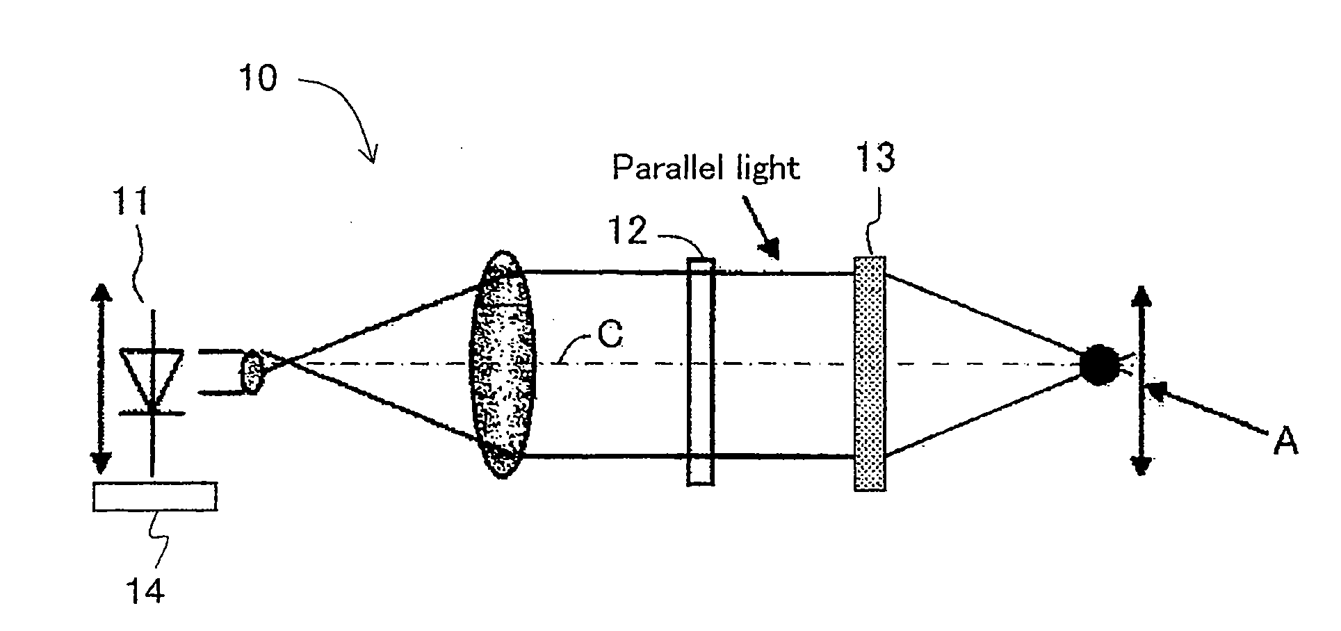
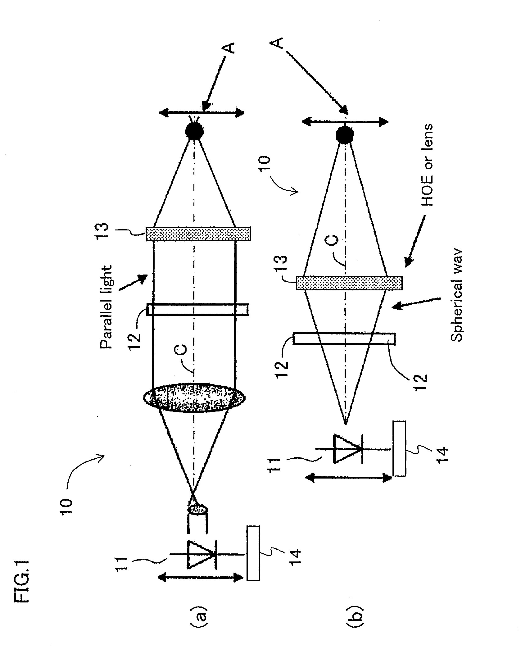
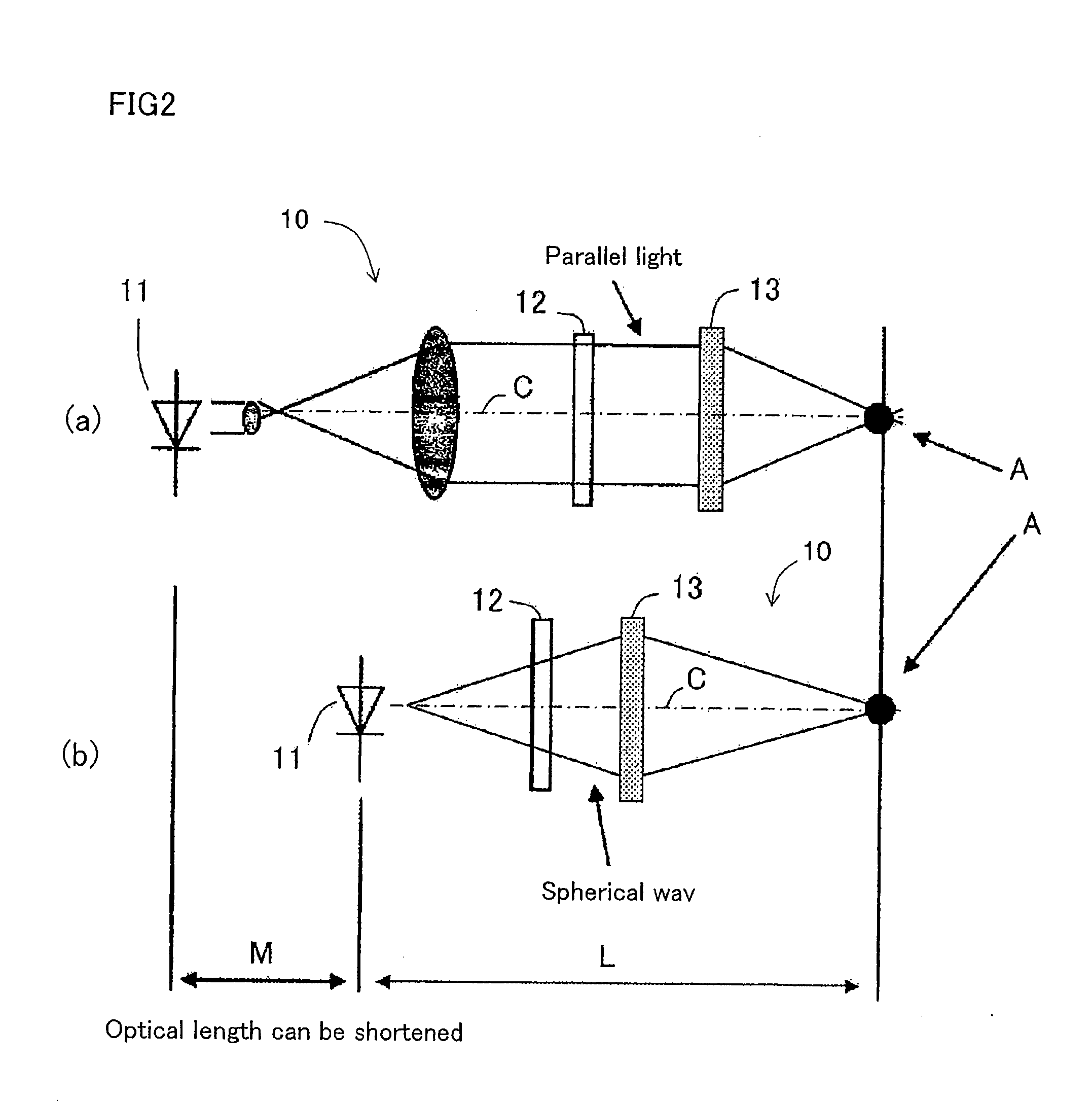
[0060]FIG. 1 is a configurational diagram showing an example of a projection-type liquid crystal display apparatus according to Embodiment 1 of the present invention. Portion (a) of FIG. 1 is a top view showing a state in which parallel light is incident on a liquid crystal display. Portion (b) of FIG. 1 is a top view showing a state in which a point light source is moved in the left-and-right direction so as to adjust the position of a light focusing convergence point.

[0061]In Portions (a) and (b) of FIG. 1, an image display apparatus 10 according to Embodiment 1 includes: a point light source 11; a liquid crystal display 12 as a liquid crystal display section for emitting display image light from a display screen using the point light source 11; a convex le...

embodiment 2

[0071]Embodiment 2 will describe a case in which light focusing converging lines other than the spherical converging light is used having the shape of a convergence point being contrived.

[0072]FIG. 5 is a configurational diagram showing an example of a lens portion of an image display apparatus according to Embodiment 2 of the present invention. Portion (a) of FIG. 5 is a perspective view of the lens portion. Portion (b) of FIG. 5 is a side view and a top view of the lens portion when focusing depths of the light focusing converging lines are the same to each other in a vertical light focusing direction and a horizontal light focusing direction. Portion (c) of FIG. 5 is a side view and a top view of the lens portion when the focusing depths of the light focusing converging lines are different from each other in the vertical light focusing direction and the horizontal light focusing direction. Members for obtaining the same working effect as those shown in FIGS. 1 and 2 are denoted w...

embodiment 3

[0078]Embodiment 3 will describe a case in which a plurality of convergence points of lenticular lenses, cylindrical lenses and the like are used.

[0079]FIG. 6 is a configurational diagram showing an example of a lens portion of an image display apparatus according to Embodiment 3 of the present invention. Portion (a) of FIG. 6 is a top view of the lens portion. Portion (b) of FIG. 6 is a side view of the lens portion. Portion (c) of FIG. 6 is a perspective view of the lens portion. Members for obtaining the same working effect as those shown in FIGS. 1 and 2 are denoted with the same reference numbers, and the description thereof will be omitted.

[0080]In Portions (a) and (b) of FIG. 6, an image apparatus 30 according to Embodiment 3 includes: the point light source 11, the liquid crystal display 12; and a lenticular lens section (lenticular lens 33) as a plurality of light focusing sections. As the lenticular lens section, a cylindrical lens 33 shown in Portion (c) of FIG. 6 can be ...


PUM


Abstract

With a simple structure, the light focusing convergence point for the Maxwellian view and the position of the pupil can be easily and quickly matched to each other in a steady manner and thus it is possible to obtain a sharp image by the Maxwellian view. When the position of the point light source 11 is automatically adjusted by the light source driving apparatus 14 using the parallel light as shown in Portion (a) of FIG. 1 as the display image light incident on the convex lens 13 (or HOE) or using the spherical wave light instead of the parallel light as shown in Portion (b) of FIG. 1, the position of the light focusing convergence point A for the Maxwellian view with respect to the position of the pupil is easily and quickly adjusted in a steady manner. Further, as with an optical path length L of the entire optical system, as shown in Portion (b) of FIG. 2, which uses the spherical wave light, it is possible to shorten the entire optical system by distance M when compared to the case, shown in Portion (a) of FIG. 2, which uses the parallel light.

Description

CROSS-REFERENCE TO RELATED APPLICATIONS[0001]This application is U.S. national phase filing under 35 U.S.C. §371 of PCT / JP2005 / 018477 filed Oct. 5, 2005 and claims priority from Japanese Application No. 2004-295400 which was filed on Oct. 7, 2004.TECHNICAL FIELD[0002]The present invention relates to: an image display apparatus for directly projecting display image light on a retina through a pupil utilizing the Maxwellian view and an electronic spectacle using the image display apparatus.BACKGROUND ART[0003]Conventionally, using the principle of a pinhole camera, the Maxwellian view converges display image light with high directivity at the position of a pupil and directly projects the display image light on the retina without focusing by a crystalline lens. Since it has a deep focusing depth, even people with low vision due to the drop of the function of the crystalline lens and a cornea can view a display image in an unblurred and sharp manner with the focus being matched at the r...

Claims


Application Information

Patent Timeline
IPC IPC(8): G03B21/53
CPCG02B27/0093G02B27/0172G02B2027/0132G02B2027/0138G02B2027/0174G02B2027/0187
Inventor TAKAHASHI, HIDEYASHIMIZU, EIJI
Owner JAPAN SCI & TECH CORP
Why Eureka
Try Eureka