Condenser microphone

a condenser microphone and microphone body technology, applied in the field of condenser microphones, can solve the problems of warped or distorted back plate, condenser microphone sensitivity characteristic can be worse, and achieve the effects of preventing excessive tension or loosening of vibration film, good sensitivity characteristic, and easy expansion and contraction

Inactive Publication Date: 2008-10-30
STAR MICRONICS
View PDF4 Cites 3 Cited by
  • Summary
  • Abstract
  • Description
  • Claims
  • Application Information

AI Technical Summary

Benefits of technology

[0026]According to this structure, the spacer is difficult to expand and contract when it is compared with a spacer made of synthetic resin, which can prevent the vibration film from being tensed or loosened excessively. Thanks to this, the condenser microphone can have a good sensitivity characteristic.
[0027]As described above, according to the invention, even when, as in a reflow soldering operation, a high temperature is applied, a condenser gap between the back plate and vibration film can be maintained constant to thereby be able to maintain the excellent sensitivity characteristic of the condenser microphone.

Problems solved by technology

However, in the condenser microphones having the conventional structure including the condenser microphone disclosed in the above-mentioned JP-A-2002-345092, since the back plate is fixed to the circuit board and vibration film support frame in the piled-up state, due to the heat in the reflow soldering operation, the spacers, back plate and the like can be warped or distorted because of the difference of the coefficients between the thermal expansion of the respective composing parts, whereby the vibration plate can be curved, the vibration plate can be tensed excessively or cannot be tensed but loosened, and a clearance between the back plate and vibration film, that is, a condenser gap can be varied; and, as a result of this, the sensitivity characteristic of the condenser microphone can be worsened.
Also, especially, when the back plate is warped and is thereby deformed greatly, or when heat is transmitted to the back plate excessively from the circuit board side, electric charges cannot be stored in an electric layer, causing a phenomenon so called “charge loss”, resulting in that the performance of the microphone can be lowered greatly.

Method used


Image

  • Condenser microphone
  • Condenser microphone
  • Condenser microphone

Examples


embodiment

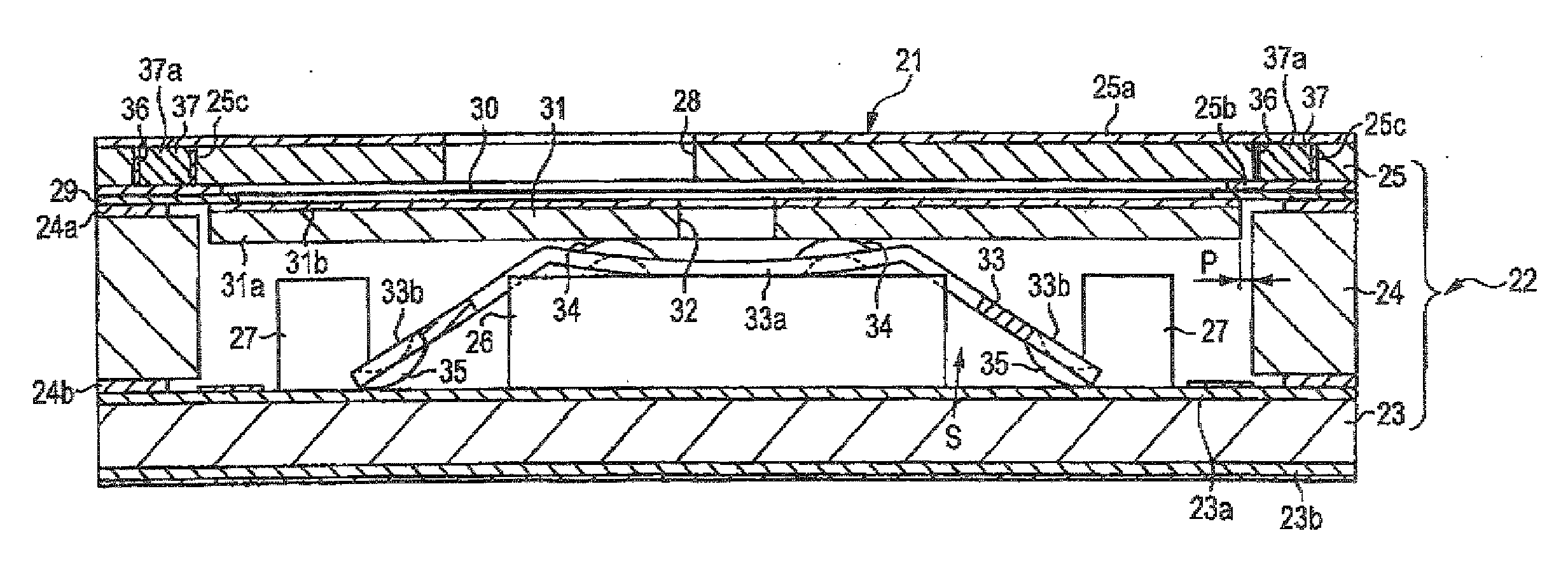
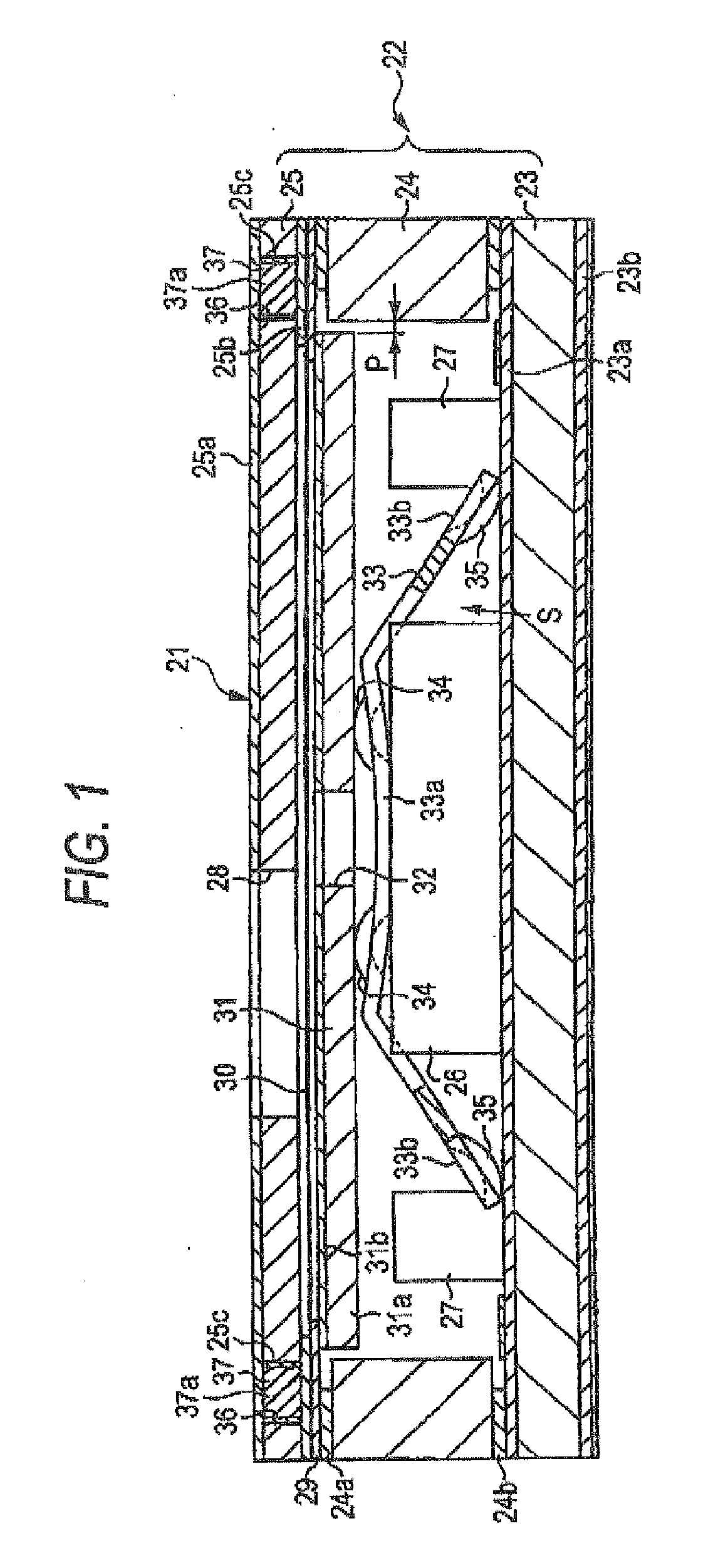
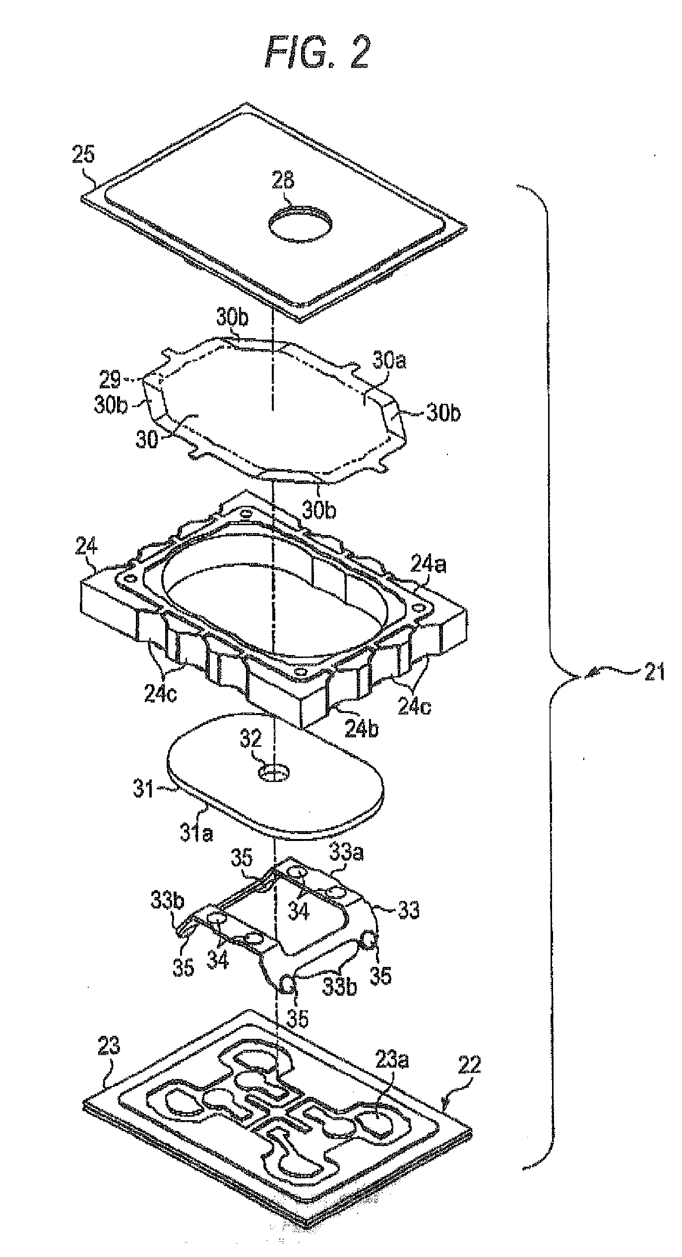
[0034]Now, description will be given below of an embodiment of a condenser microphone according to the invention with reference to FIGS. 1 to 3.

[0035]As shown in FIGS. 1 and 2, a condenser microphone 21 according to the present embodiment includes a casing 22. The casing 22 is structured such that a circuit board 23 formed in a flat plate shape, a casing base frame 24 formed in a square frame shape, a top plate 25 formed in a flat plate shape are sequentially piled up and also that these parts are fixed together with adhesive into a unified body. The circuit board 23, casing base frame 24 and top plate 25 are respectively made of electric insulation material such as epoxy resin, liquid crystal polymer, ceramic or the like. On the upper and lower surfaces of the circuit board 23, there are printed conductive patterns 23a and 23b made of copper foils or the like, respectively. And, on the circuit board 23, there are mounted electronic components such as a field-effect transistor 26 an...


PUM


Abstract

A condenser microphone includes: a casing including a sound hole; a vibration film disposed in the casing so as to face the sound hole; a back plate disposed opposed to the vibration film; a spacer disposed between the vibration film and the back plate; and a hold member including a spring member. The back plate has an outer peripheral shape that is smaller than an inner peripheral shape of the casing so as to provide a clearance between an outer peripheral surface of the back plate and an inner peripheral surface of the casing. The back plate is held by the hold member from an opposite side of the vibration fills.

Description

BACKGROUND OF THE INVENTION[0001]1. Field of the Invention[0002]The present invention relates to a condenser microphone which is used in equipment such as a cell phone, a video camera and a personal computer.[0003]2. Background Art[0004]Conventionally, as a condenser microphone of this type, for example, there is proposed a condenser microphone which is structured as disclosed in JP-A-2002-345092. That is, this conventional condenser microphone is structured such that a circuit board with electronic components mounted thereon, a lower spacer, a back plate having a back electrode, an upper spacer, and a vibration film support frame with a vibration film carried on the lower surface thereof are piled up and fixed sequentially in order starting from the bottom portion of the condenser microphone.[0005]Here, in this type of condenser microphone including the condenser microphone disclosed in JP-A-2002-345092, after the respective composing parts thereof are piled up and assembled in the...

Claims


Application Information

Patent Timeline
Patent Type & Authority Applications(United States)
IPC IPC(8): H04R11/04
CPCH04R19/04
Inventor YONEHARA, KENTAROIMAHORI, YOSHIOTSUKUDA, YASUNORIITO, MOTOAKI
Owner STAR MICRONICS
Why Eureka
Try Eureka