Heat Treating Apparatus

Active Publication Date: 2008-10-30
KOKUSA ELECTRIC CO LTD +1
View PDF0 Cites 356 Cited by
  • Summary
  • Abstract
  • Description
  • Claims
  • Application Information

AI Technical Summary

Benefits of technology

[0028]The invention according to the above item (1) is capable of supporting the substrate so that the amount of the substrate displacement (deflection) is minimal. Moreover, when supporting the substrate in that state, the invention is capable of preventing both slips due to from protrusions on the surface of the support plate, and slips due to the adhesive force occurring due to excessive smoothing of the support plate surface.
[0029]The invention according to the above item (2) is capable of reliably preventing both slips when supporting the substrate so that the amount of the substrate deflection is minimal.
[0030]The invention according to the above item (3) is capable of preventing both slips to an

Problems solved by technology

However, boats with this type of stru

Method used


Image

  • Heat Treating Apparatus
  • Heat Treating Apparatus
  • Heat Treating Apparatus

Examples


Embodiment Construction

[0054]An embodiment of the present invention is described next while referring to the accompanying drawings.

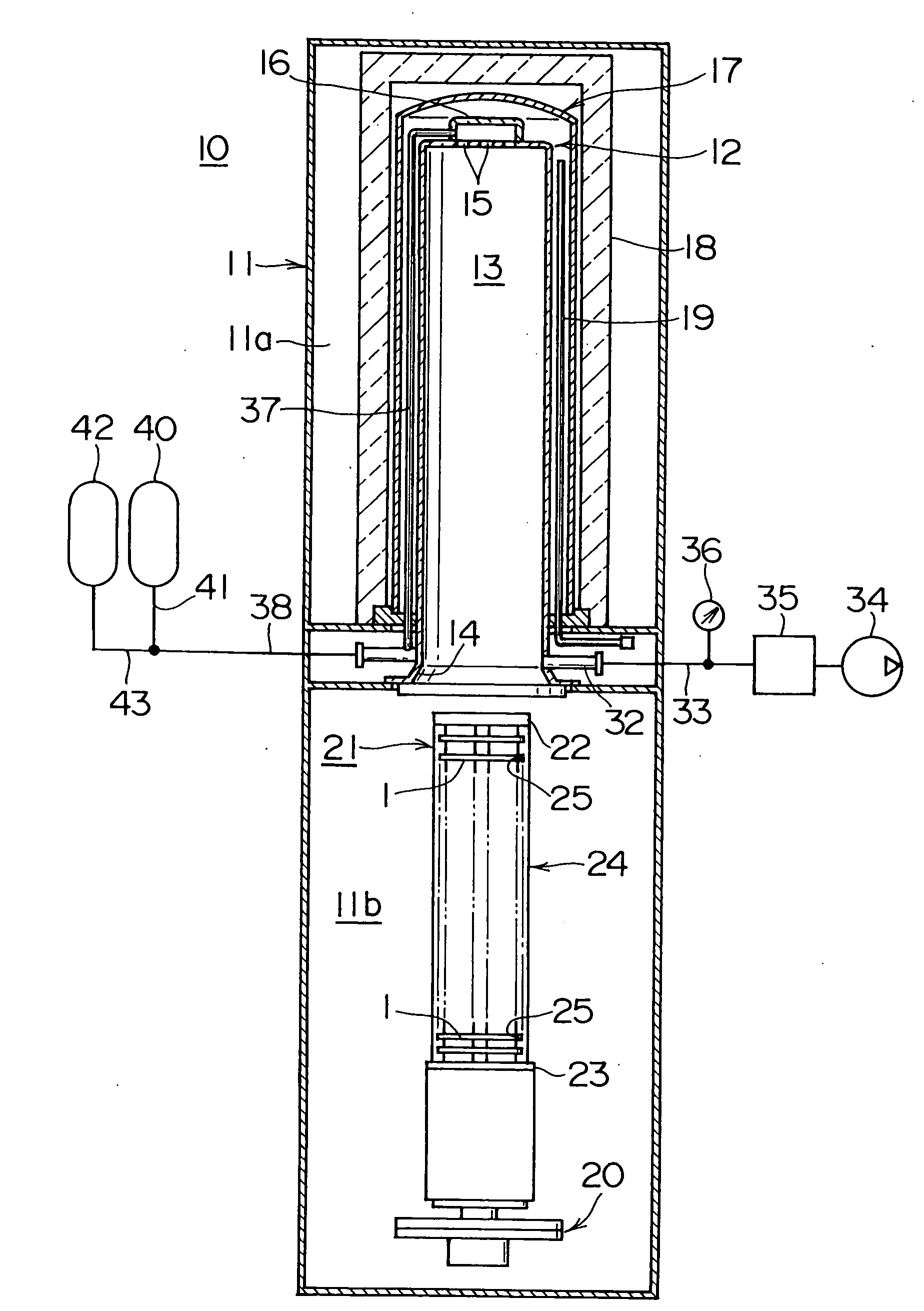
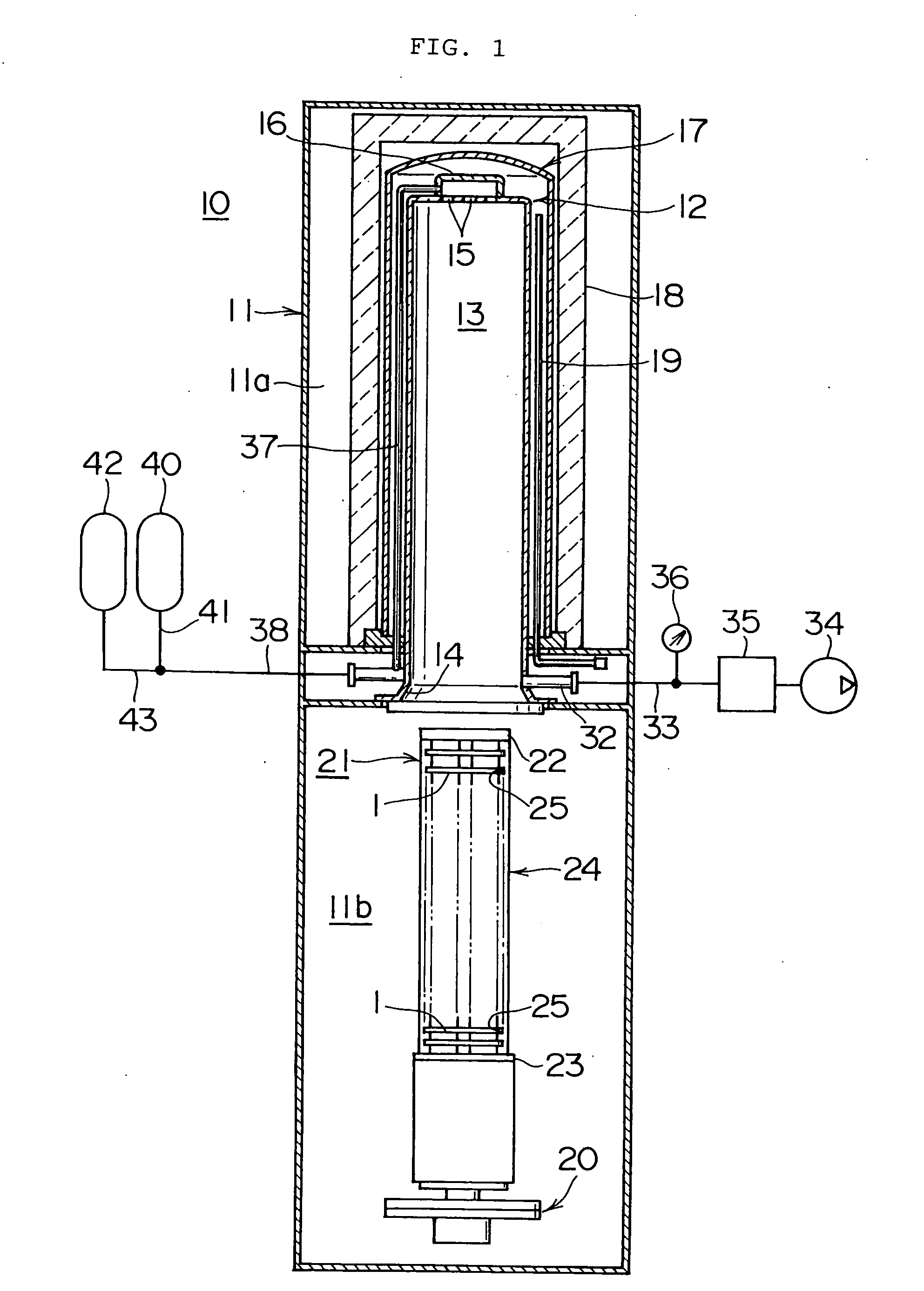
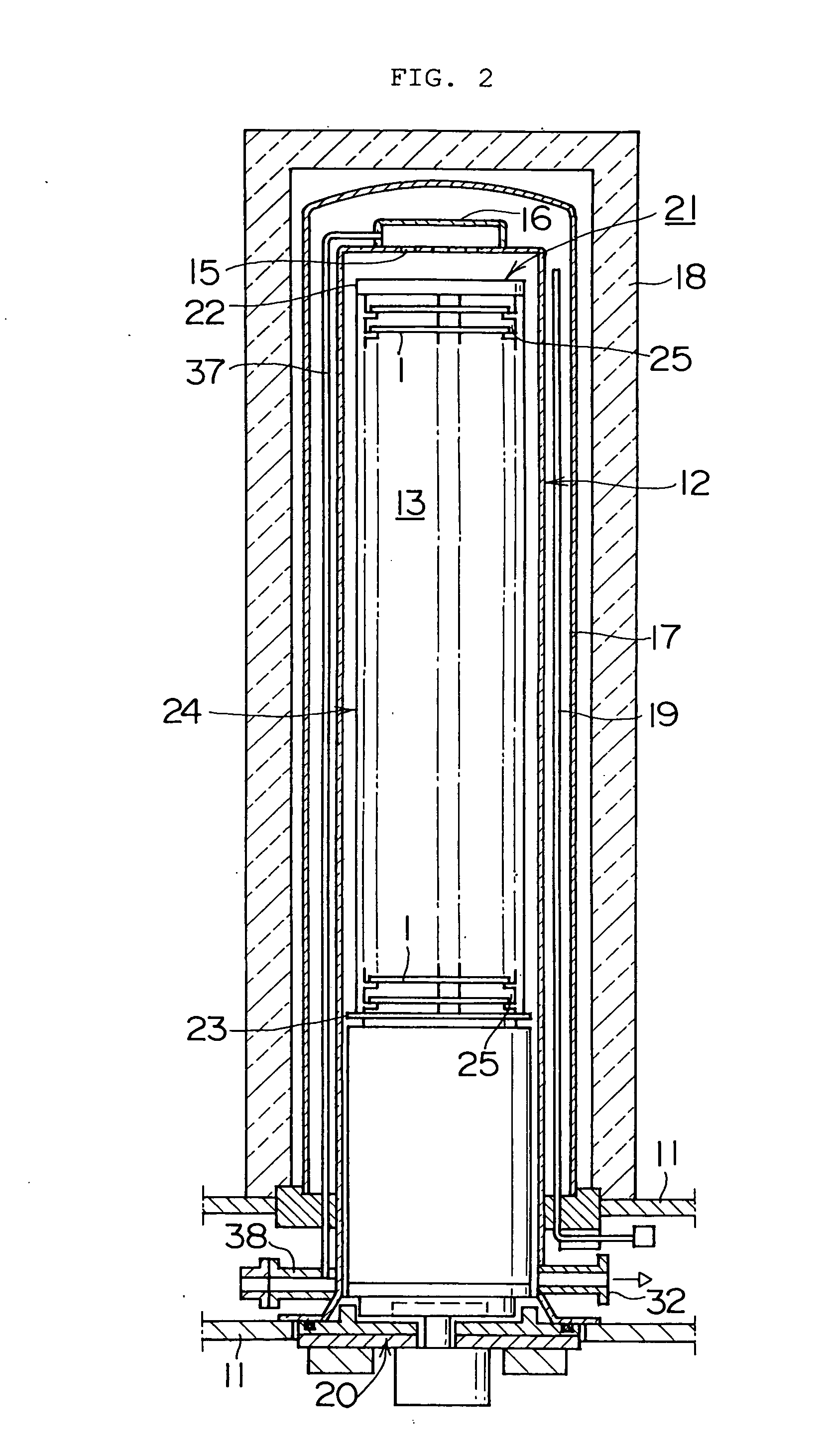
[0055]In the present embodiment, the heat treating apparatus of the present invention is structurally comprised of a heat treating apparatus (batch type vertical hot-wall heat treating apparatus) as shown in FIG. 1 and FIG. 2; and functionally is comprised of a dry oxidizing device (hereafter simply called an oxidizing device) as one type of oxidation film forming apparatus for forming an oxidization film on a wafer.

[0056]An oxidizing device 10 contains a process tube (reaction tube) 12. The process tube 12 is made from quartz (SiO2) or silicon carbide (SiC) and formed in an integrated cylindrical shape with the bottom end opened and the top end closed. The process tube 12 is installed vertically so that its centerline is perpendicular and is supported by an installation chamber 11a at the upper portion of a case 11.

[0057]The hollow section within the process tube 12 forms a p...


PUM


Abstract

[Problems] To prevent both slips caused by damage from projections, and slips caused by adhesive force occurring due to excessive smoothing.
[Means for Solving the Problems] The heat treating apparatus includes a processing chamber for heat treating wafers and a boat for supporting the wafers in the processing chamber. The boat further includes a wafer holder in contact with the wafer and a main body for supporting the wafer holder. The wafer holder diameter is 63 to 73 percent of the wafer diameter, and the surface roughness Ra of the portion of the wafer holder in contact with the wafer is set from 1 μm to 1,000 μm. The wafer can be supported so that the amount of wafer displacement is minimal and both slips due to damage from projections on the wafer holder surface, and slips due to the adhesive force occurring because of excessive smoothing can be prevented in that state.

Description

TECHNICAL FIELD[0001]The present invention relates to a heat treating apparatus and relates in particular to technology for supporting the substrate for processing, and for example, relates to technology effective in the heat treatment process performed at a comparatively high temperatures to thermally treat the semiconductor wafer (hereafter called, wafer) where the IC is formed in a method for manufacturing semiconductor integrated circuit devices (hereafter called IC).BACKGROUND ART[0002]A batch type vertical hot-wall heat treating apparatus is widely used in heat treatment processes such as oxidizing, diffusion or annealing process applied to the wafer at comparatively high temperatures in IC manufacturing methods.[0003]This batch type vertical hot-wall heat treating apparatus (hereafter called, heat treating apparatus) includes a process tube installed vertically to form the processing chamber where the wafers are carried in; a heater unit for heating the processing chamber out...

Claims


Application Information

Patent Timeline
IPC IPC(8): A21B2/00H01L21/00H01L21/22H01L21/31H01L21/324H01L21/68
CPCH01L21/324H01L21/67109H01L21/67306H01L21/67309
Inventor NAKAMURA, IWAONAKAMURA, NAOTONAKASHIMA, SADAO
Owner KOKUSA ELECTRIC CO LTD
Why Eureka
Try Eureka