
Performance maps for actuator intelligence

Inactive Publication Date: 2008-10-30
TESAR DELBERT
View PDF5 Cites 21 Cited by
  • Summary
  • Abstract
  • Description
  • Claims
  • Application Information

AI Technical Summary

Benefits of technology

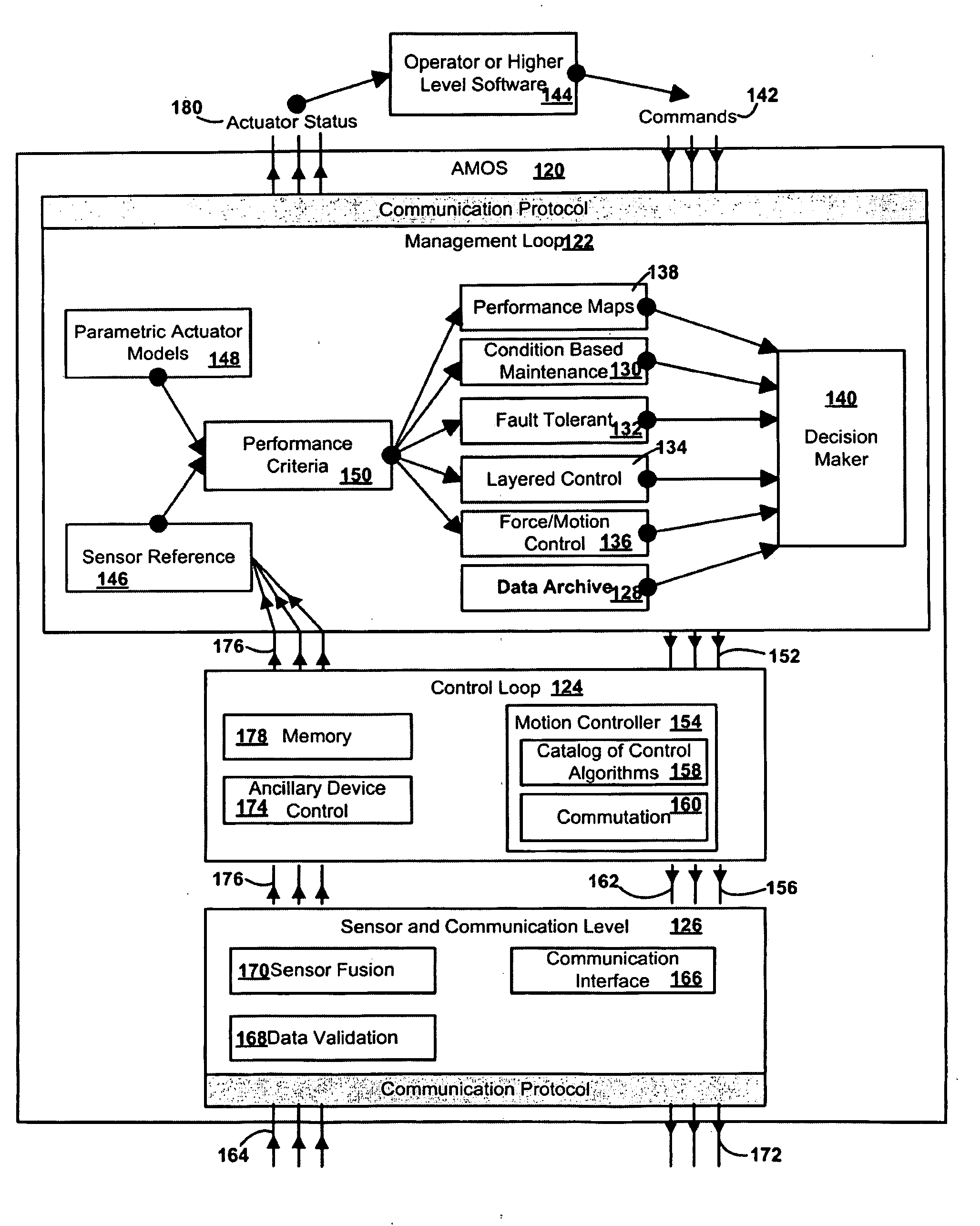
[0013]According to one aspect of the present disclosure, a four level fault tolerant architecture for the intelligent machine system based on the basic component of a self contained actuator module with standardized interfaces. This system architecture then organizes all of the operational software development to not only make it universal for all configurations under this architecture but to also make high performance, fault tolerance and condition-based maintenance possible. In the present disclosure, the system level and module levels are split into four independent structural layers which will be structured and prioritized by the advanced electronic controllers. The sensor module will be used to create an accurate parametric representation of the “as-built” electro-mechanical actuator through extensive testing, and mange all resources in the electro

Problems solved by technology

However, the basic module of these systems is the actuator, and actuator technology has been stagnant for decades, and the re-configurability at this system level does not exist.
Consequently, the systems weigh too much, exhibit too much backlash, too much rotary inertia, and too little stiffness; they also remain expensive with no interface standards to make their utilization in larger systems logical and cost effective.
Lack of progress is primarily due to the inattention to the intelligent actuator which serves as the connection between the computer and the physical task.
Unfortunately, electrical prime movers combined in a full and balanced architecture with gear transmissions, brakes, clutches, sensors, electronic controllers, and decision making software have not been given sufficient attention by scientists and engineers to make them sufficiently competitive with alternate technical solutions (hydraulics, pneumatics) except in special applications.
A major missing piece to electro-mechanical actuators is the lack of best duty cycle information with performance characteristics of the electro-mechanical actuator.
Without sufficient sensors to measure actuator outputs, there has been very little awareness of the true capabilities of the actuator, and the electro-mechanical actuator is typically restrained to operation in the conservative range.
Like other systems that would benefit from intelligent electro-mechanical actuators, commercial aircraft are increasingly complex with more fly-by-wire technology, more communications equipment, and higher safety standards.
Uncertainty associated with maintenance, false alarms, and sudden failures are all costly problems with current technology employed in aircraft.
As well as being complex, these systems are heavier than an intelligent electrical actuator alternative.
Failure points in the traditional system have led to fault tolerance, which implies redundancy, but also drives up weight and cost.
The data is not sufficient to describe the actuator completely, and results in failures going undetected by operators and maintenance crews.
Mechanical devices are highly non-linear and their operational parameters drift over time due to aging, and extended operation.
Increasingly, these devices are becoming more complex, and the user community wants continued improved performance at lower cost.
This demand requires the operation of mechanical devices closer to the operational margins of that device, and that classical methods of control based on simplistic linearized models can no longer be the basis for continued growth in the technology.
The components of these actuators are unique to each system, and are incapable of reconfiguration, repair, and maintenance.
As well, the systems are lacking in their ability to operate at efficient rates due to a lack of developed performance characteristics.

Method used


Image

  • Performance maps for actuator intelligence
  • Performance maps for actuator intelligence
  • Performance maps for actuator intelligence

Examples


Embodiment Construction

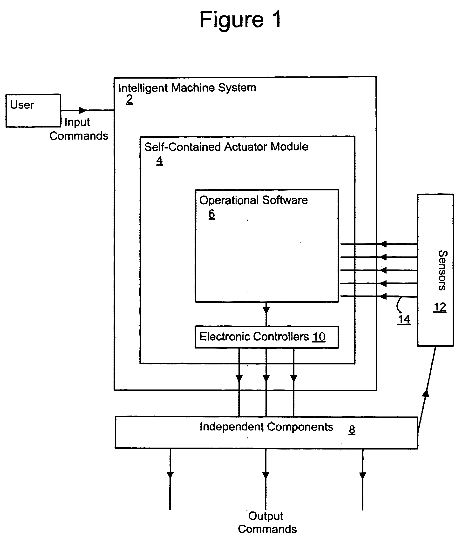
[0022]The present disclosure, represented in FIG. 1, is a four level fault tolerant architecture for the intelligent machine system 2 based on the basic component of a self-contained actuator module 4 with standardized interfaces. This system architecture then organizes all of the operational software 6 development to not only make it universal for all configuration under this architecture but to also make high performance, fault tolerance, and condition-based maintenance possible. Similar generality is also present in the actuator itself. At the system level, there are four independent structural layers, and the same will occur within the actuator. Multiple independent components 8 (magnetic circuits, poles, magnets, etc.) will be structured and prioritized by advanced electronic controllers 10 (in hundredths of a millisecond) which are in themselves redundant and reconfigurable. Multiple sensors 12 monitor these components, and send Feedback 14 into the operational software 6. The...


PUM


Abstract

A four level fault tolerant architecture for the intelligent machine system is based on the basic component of a self contained actuator module with standardized interfaces. This system architecture organizes all of the operational software to make it universal, high performing, fault tolerant, and use condition-based maintenance. The independent structural layers are structured and prioritized by the advanced electronic controllers. The sensor module creates an accurate parametric representation of the electro-mechanical actuator, and manages all resources in the electro-mechanical actuator. The system will also comprise of operational criteria, maximum performance envelopes, condition-based maintenance, fault tolerance, layered control, and force / motion control. The system allows independent development of different components of the framework, categorized into three levels: the management level, the servo control level, and the senor and communication level. The present disclosure establishes a fully responsive actuator whose intelligence manages a sufficiently broad set of choices.

Description

RELATED APPLICATIONS[0001]This application claims the benefit of priority to U.S. Provisional Patent Application No. 60 / 914,211 entitled “PERFORMANCE MAPS FOR ACTUATOR INTELLIGENCE,” by Dr. Delbert Tesar filed on Apr. 28, 2007, and is incorporated herein by reference in its entirety for all purposes.FIELD[0002]The disclosed subject matter relates to mechanical systems for the transfer and control of motive forces and control of such systems and processes. More particularly, this disclosure relates to a novel and improved method and system for making, using, and improving performance maps for actuator intelligence as may be apply to a broad array of standardized and other rotary, linear, and other types of actuator devices and systems employing such devices.DESCRIPTION OF THE RELATED ART[0003]Dexterous intelligent machines can be reconfigured, repaired, or maintained by rapid replacement of modules, and is one of their successful attributes. However, the basic module of these systems...

Claims


Application Information

Patent Timeline
IPC IPC(8): G05B13/02
CPCG05B13/02G05B2219/45207
Inventor TESAR, DELBERT
Owner TESAR DELBERT
Learn More