Eureka AIR delivers breakthrough ideas for toughest innovation challenges, trusted by R&D personnel around the world.

Automatic Switching Two Pipe Hydronic System

Inactive Publication Date: 2008-11-06
BLECKER JOSEPH G
View PDF60 Cites 28 Cited by
  • Summary
  • Abstract
  • Description
  • Claims
  • Application Information

AI Technical Summary

Benefits of technology

[0009]In one aspect, the present invention provides an automatic switching two pipe hydronic system. The system comprises: a supply line; a return line; a primary boiler; a secondary boiler; a heat exchanger; a primary chiller; a secondary chiller; a cooling tower; at least one closed loop pump; a plurality of flow control valves; a plurality of sensors; and a controlling module. The supply line is configured to supply a conditioned fluid to a space. The return line is configured to return utilized conditioned fluid from the space. The primary boiler is in fluid communication with the supply line and the return line and capable of operating in a first full load condition. The secondary boiler is in fluid communication with the supply line and the return line and the secondary boiler is capable of operating in a first part load condition. The heat exchanger is in fluid communication with the supply line and the return line and the heat exchanger is configured to transfer heat between the return line and the supply line. The primary chiller is in fluid communication with the supply line and the return line, capable of operating in a second full load condition. The secondary chiller is in fluid communication with the supply line, and the return line and the secondary chiller is capable of operating in a second part load condition. The cooling tower is in fluid communication with the heat exchanger; the primary chiller; and, the secondary chiller. The cooling tower is configured to take away heat from the heat exchanger, the primary chiller and the secondary chiller. The closed loop pump has a variable speed drive and the closed loop pump is capable of regulating the flow between the return line and the supply line. The flow control valves are disposed in the supply line and the return line. The flow control valves are capable of controlling the flow of fluid through the supply and return line and the primary boiler, the secondary boiler, the heat exchanger, the primary chiller, the secondary chiller, and the cooling tower. The sensors are configured for sensing an outside space temperature, an inside space temperature, and temperature of the fluid in the supply line and the return line. The controlling module is configured to acquire temperatures from the plurality of sensors and is capable of controlling the flow of fluid through the flow control valves.
[0010]In another aspect, the present invention provides a method for automatically switching a first mode of operation to a second mode of operation during conditioning a space by conditioning a return fluid in a return line to be supplied as a supply fluid in a supply line of a system having a primary boiler, a secondary boiler, a heat exchanger, a primary chiller, a secondary chiller, a cooling tower and a closed loop pump. The method comprises: switching the primary boiler providing heated supply fluid in the first mode of operation to a standby mode upon determining an increase in an outside space temperature; switching the secondary boiler to an operational mode for reducing the temperature of the supply fluid in the supply line by heating the return fluid from the return line in the secondary boiler to a temperature less than the temperature of the heated supply fluid; disabling the secondary boiler and enabling a variable speed drive of the closed loop pump for regulating the flow of supply fluid to the supply line; enabling the heat exchanger for reducing the temperature of the return fluid in the return line to be supplied as the supply fluid in the supply line by transferring heat of the return fluid to the cooling tower; disabling the heat exchanger and enabling the secondary chiller for reducing the temperature of the return fluid in the return line to be supplied as the supply fluid in the supply line by transferring heat of the return fluid to the cooling tower; enabling the primary chiller and receiving the fluid from the secondary chiller into the primary chiller for reducing the temperature of the fluid from the secondary chiller to be supplied as the supply fluid in the supply line by transferring heat of the fluid from the primary chiller to the cooling tower; and disabling the secondary chiller for switching the system to the second mode of operation.
[0011]In another aspect, the present invention

Problems solved by technology

A disadvantage to the '152 disclosure is that requires the installation of an additional component to the existing HVAC system.
The '482 patent does not address the diverse and localized needs within large spaces, such as where a large space will require cooling in one area and heating in another area.
The '715 disclosure fails to address the diverse and localized needs within large spaces, such as where a large space will require cooling in one area and heating in another area.
Notwithstanding these efforts, the prior art fails to improve the functionality and adjustability of HVAC systems to meet today's needs of energy conservation and quick changeover from heating to cooling in a space and of being able to provide heating and cooling at the same by the same system.

Method used


Image

  • Automatic Switching Two Pipe Hydronic System
  • Automatic Switching Two Pipe Hydronic System
  • Automatic Switching Two Pipe Hydronic System

Examples


Embodiment Construction

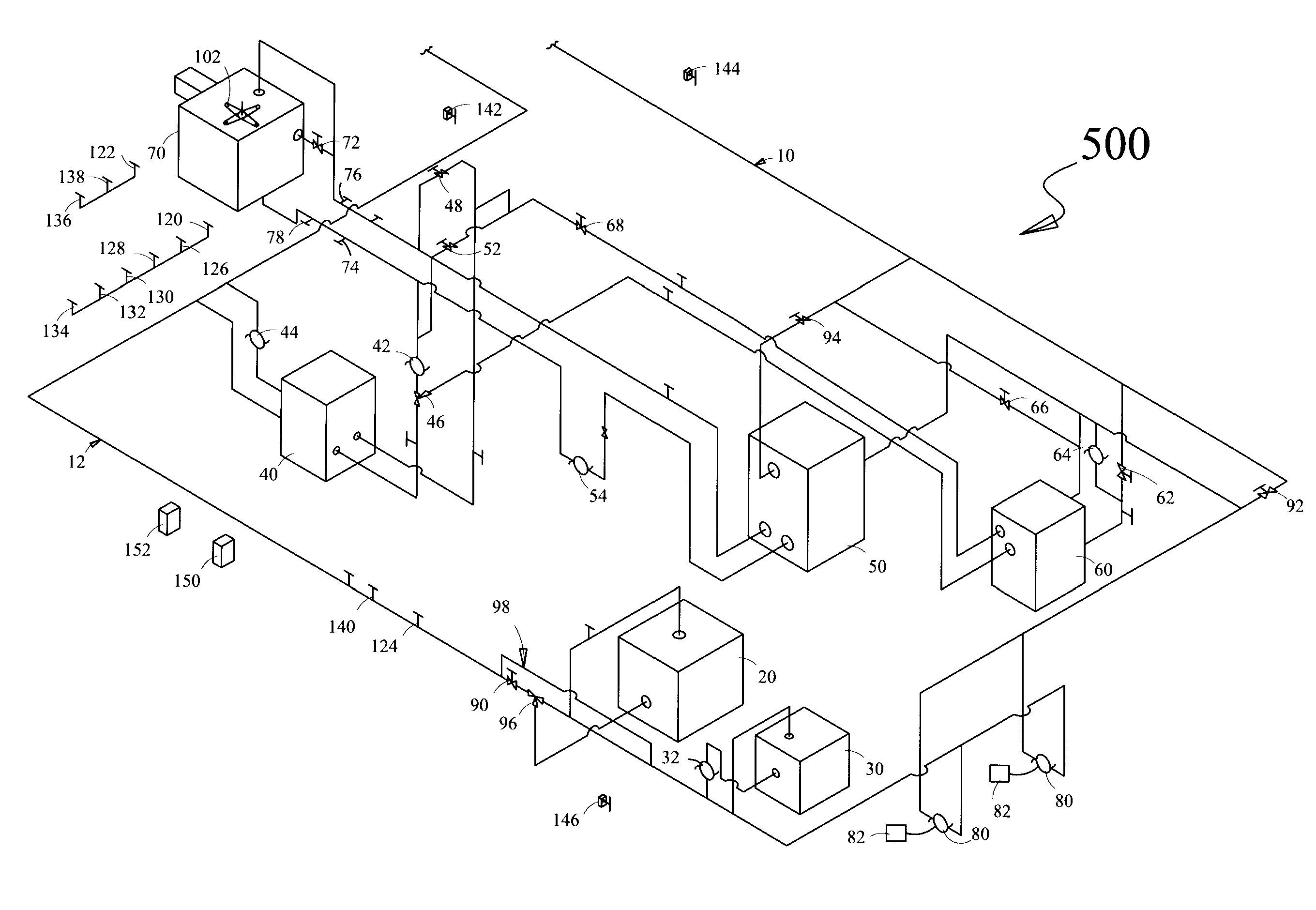
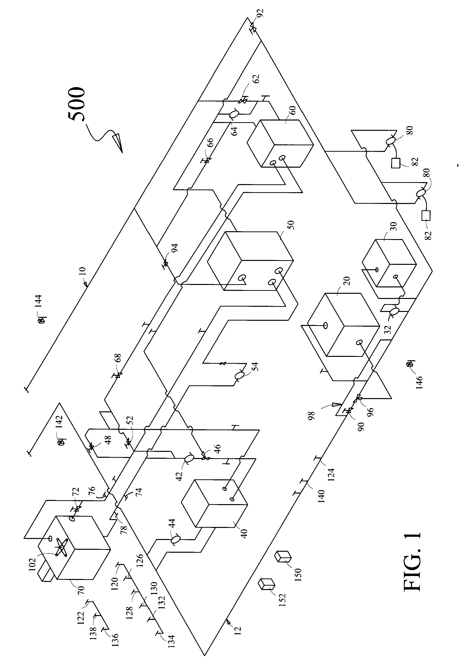
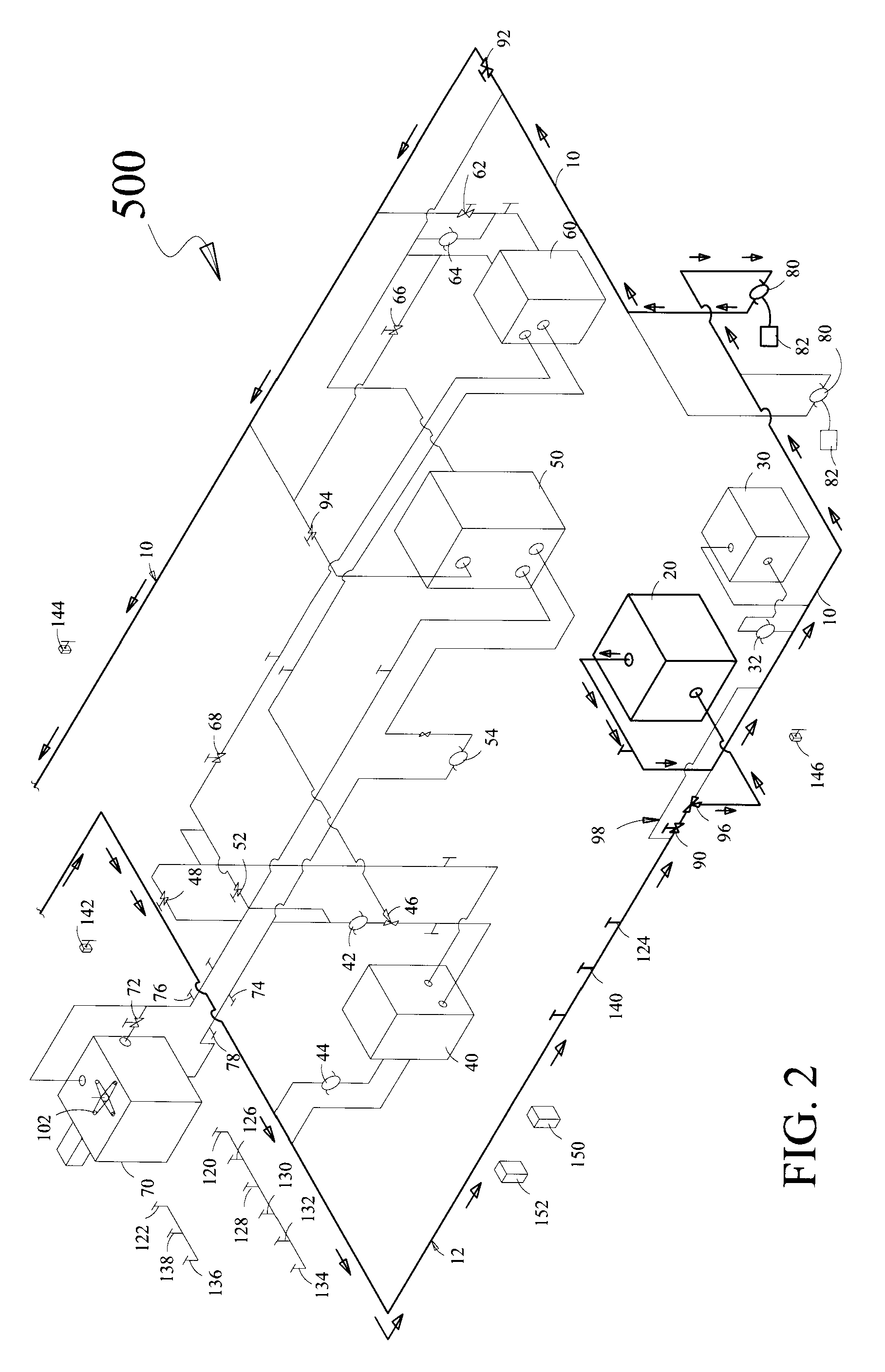
[0028]The exemplary embodiments described herein detail for illustrative purposes are subject to many variations in structure and design. It should be emphasized, however, that the present invention is not limited to an automatic switching two pipe hydronic system as shown and described. It is understood that various omissions, substitutions, and equivalents are contemplated as circumstances may suggest or render expedient, but it is intended to cover the application or implementation without departing from the spirit or scope of the claims of the present invention. The terms “a”, an “first”, and “second”, herein do not denote a limitation of quantity, but rather denote the presence of at least one of the referenced item.

[0029]It should be noted that the various temperature ranges and corresponding operational set points discussed herein are for illustrative purposes only and that the particular set points and temperature ranges will depend on the particular geographic location and ...


PUM


Abstract

Disclosed is an automatic switching two pipe hydronic system for conditioning a space. In one embodiment the two pipe hydronic system enables automatic switching from a first mode of operation to a second mode of operation or vice versa in a reduced span of time. The present invention saves fuel, energy and water, when there are lower load conditions that affect boilers, chillers, and cooling towers. In another embodiment, the present invention provides a system for simultaneously heating and cooling a first portion and a second portion of a space by utilizing a plurality of boilers, chillers, heat exchangers, condenser pumps and closed loop pumps by using a plurality of sensors indicating the temperatures inside and outside the space and a controlling module controlling the operation of the system. The present invention can be easily achieved by making minor configurational modifications to existing systems thereby increases system versatility.

Description

FIELD OF THE INVENTION[0001]The present invention relates to air-conditioning systems and more particularly relates to an automatic switching two pipe hydronic system for conditioning a space.BACKGROUND OF INVENTION[0002]Space heating is a component of heating, ventilation, and air conditioning (HVAC) and is a predominant mode of conditioning space. Depending on the local climate, space heating is in operation up to and beyond seven months out of the year. During the time of such operation, there will be numerous occasions when cooling of the space will be needed to prevent discomfort and lost productivity of inhabitants of such space. Thus, the adjustability of HVAC systems is desirable. Space heating has traditionally been accomplished by two-pipe systems that incorporate a hot water boiler.[0003]One approach to improve the adjustability of HVAC systems is shown by U.S. Pat. No. 4,360,152, which discloses an auxiliary heating system for reducing fuel consumption of a conventional ...

Claims


Application Information

Patent Timeline
IPC IPC(8): F25B29/00G05D23/00
CPCF24F3/06F25B29/003
Inventor BLECKER, JOSEPH G.
Owner BLECKER JOSEPH G
Why Eureka
Eureka Blog
Learn More