Sensing System Using Optical Fiber Suited to High Temperatures

a sensing system and high temperature technology, applied in the field of sensing systems, sensing methods, optical fiber sensing and suited to high temperature environments, can solve problems such as longer useful life, and achieve the effect of good protection

Active Publication Date: 2008-11-06
SENSORNET
View PDF13 Cites 135 Cited by
  • Summary
  • Abstract
  • Description
  • Claims
  • Application Information

AI Technical Summary

Benefits of technology

[0016]By using a larger diameter cladding than usual, the effects of stress from the metallic protective layer can be reduced. By reducing the stress, lower optical loss can be achieved because the modal stress perturbations can be reduced. This means sensing measurements can be more accurate, and useful life of the fiber can be increased. This is particularly valuable for applications such as bore holes where it can be extremely expensive to replace the fiber. Furthermore, lower stress can result in a better yield during manufacturing and thus lead to longer continuous lengths and thus less need for fiber splices which are expensive and vulnerable to damage. The increased diameter can also impede the effect of any metal or gas diffusion reaching interacting with the light propagating in the core of the fiber and thus lead to longer useful life. It can also facilitate accommodating multiple cores within the same fiber.
[0054]This can enable a cost reduction compared to using two fibers or a multi-core fiber, which is particularly valuable for more expensive fibers suitable for high temperature environments. The fiber life is also increased since risk of fiber deterioration causing loss of sensing is reduced since there is half the length in the harsh environment.

Problems solved by technology

The increased diameter can also impede the effect of any metal or gas diffusion reaching interacting with the light propagating in the core of the fiber and thus lead to longer useful life.

Method used


Image

  • Sensing System Using Optical Fiber Suited to High Temperatures
  • Sensing System Using Optical Fiber Suited to High Temperatures
  • Sensing System Using Optical Fiber Suited to High Temperatures

Examples


Embodiment Construction

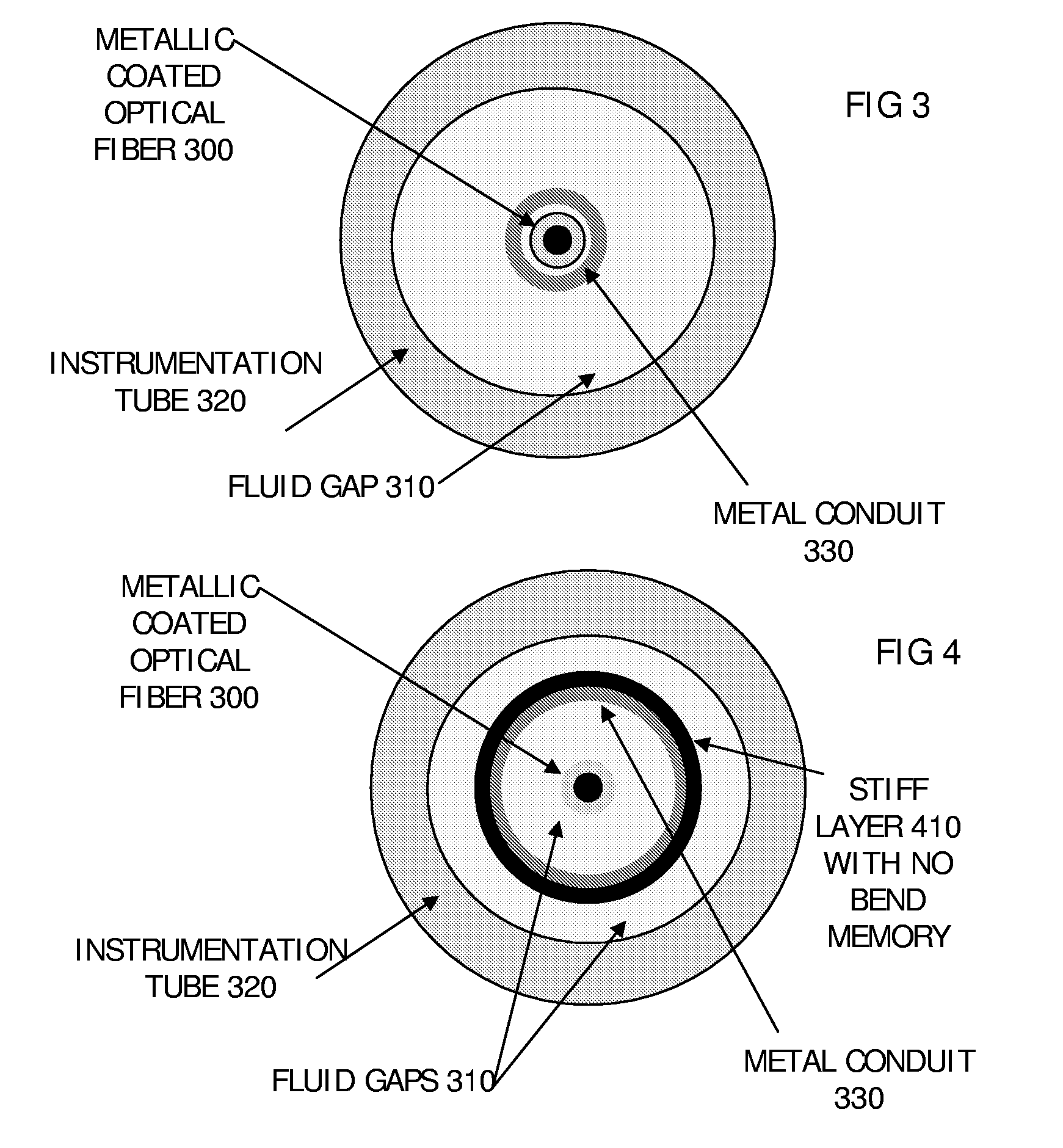
FIGS. 1-5, Sensing Cables for High Temperature

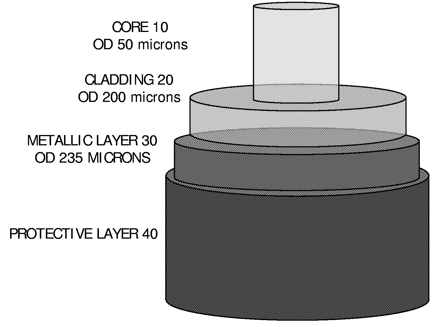
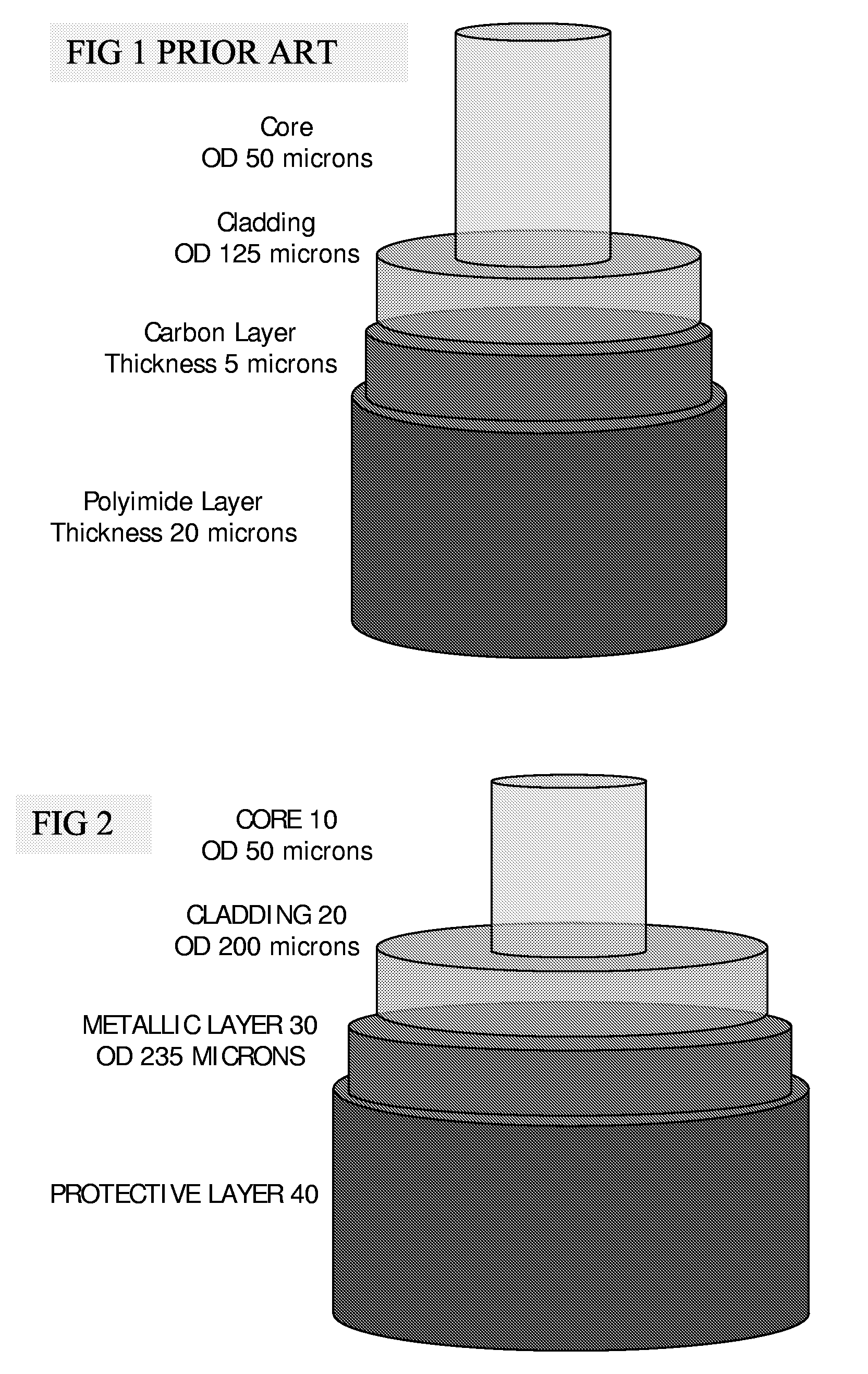
[0070]By way of introduction to the embodiments, a known fiber will be described. FIG. 1 shows a typical known sensing fiber which has a core of 50 μm, a cladding of 125 μm, a protective layer of carbon, of thickness of 5 μm, and an outer protective layer of polyimide of thickness of 20 μm. This can be manufactured using established techniques.

High Temperature Fiber Factors

[0071]The coatings of FIG. 1 are typically rated to 300° C. under ideal conditions. However, it appears that once these fibers are installed inside oil wells, they are failing at temperatures lower than 200° C. This is believed to be due to a combination of two factors.

1. During the pumping installation technique the fiber coating is prone to damage which reduces the level of protection to the fiber. Even in low temperature applications, there has been extensive degradation. It should be noted that pumping requires a flexible, lightweight fiber and so, by necessity, th...


PUM

PropertyMeasurementUnit
thicknessaaaaaaaaaa
thicknessaaaaaaaaaa
temperaturesaaaaaaaaaa

Abstract

Remote sensing in an environment having temperatures greater than 300° C., using an optical fiber having a core (10), a cladding (20), and a metallic protective coating (30) on the cladding to protect a surface of the cladding, the cladding having a diameter greater than 150 μm, and a thickness of at least 50 μm. The larger diameter cladding means stress from the metallic protective layer can be reduced, giving lower optical loss and better hydrogen protection. A metal conduit (330) encapsulates the sensing fiber, and a pump evacuates the conduit to reduce hydrogen seepage. Ceramic splice protectors are used. OTDR is used to determine differential loss at different locations along the fiber. A reflective element at the far-end of the fiber eases calibration.

Description

RELATED APPLICATIONS[0001]The present invention relates to previously filed cases entitled “Method and Apparatus for Generation and Transmission of High Energy Optical Pulses for Long Range Measurements”, publication WO 2004 / 073172, (ref SENS 006), filed 11 Feb. 2004, “Direct Measurement of Brillouin Frequency in Distributed Optical Sensing Systems” Publication WO2005 / 1006396, (ref SENS 007) filed 22 Mar. 2005, and “Intervention Rod”, PCT application no PCT / GB2005 / 050107, filed 7 Jul. 2005 (ref SENS 008), all incorporated herewith by reference in their entirety.FIELD OF THE INVENTION[0002]The present invention relates to sensing systems, methods of sensing, and optical fibers for sensing and suited to high temperature environments.BACKGROUND[0003]There is a requirement in industry for the measurement of conditions such as strain or temperature and other conditions at all points over long distances. Typical uses are for monitoring oil and gas wells, long cables and pipelines. The mea...

Claims


Application Information

Patent Timeline
Patent Type & Authority Applications(United States)
IPC IPC(8): G02B6/02
CPCG01J5/08G01J5/0821G02B6/2558G01D5/3538G02B6/4436G02B6/4492G02B6/4402E21B47/113G02B6/44382G01D5/268G01D5/353
Inventor PARKER, TOM RICHARDFARHADIROUSHAN, MAHMOUDMONDANOS, MICHAIL
Owner SENSORNET
Why Eureka
Try Eureka