Method and apparatus for low chirp transmitter for optical fiber communications

a low-chirp, optical fiber technology, applied in the direction of electromagnetic transmission, electromagnetic transceivers, multi-component communication, etc., can solve the problems of difficult suppression of stimulated brillouin scattering (sbs), high cost, and difficult modulation depth of external modulated transmitters, etc., to achieve low-chirp in the transmitter, suitable for optical fiber networks

Inactive Publication Date: 2008-11-06
ATX NETWORKS (TORONTO) CORP
View PDF11 Cites 26 Cited by
  • Summary
  • Abstract
  • Description
  • Claims
  • Application Information

AI Technical Summary

Problems solved by technology

Although such analog transmission techniques have the advantage of substantially smaller bandwidth requirements than digital transmission, such as digital pulse code modulation, or analog or pulse frequency modulation, such use of amplitude modulation tends to suffer from noise and nonlinearity of the optical transmitter.
Externally modulated transmitters are more complex, expensive and have lower modulation depth (are less linear) than directly modulated transmitters.
Also, suppression of stimulated Brillouin scattering (SBS) is difficult.
Disadvantageously, heretofore they do not work well at the 1550 nm optical wavelength.
They do work well at the 1310 nm wavelength, however optical amplifiers for 1310 nm light are generally not commercially available, making 1310 nm difficult to use.
The issue with chirp is that it interacts with the dispersion in the optical fiber to produce undesirable distortions, primarily CSO (Composite Second Order) distortions, that fall in band in multi-octave (wideband) systems such as cable television.
In addition to being limited to the external cavity type laser, it appears that chirp correction here would be inadequate for a directly modulated laser (e.g., DFB) which generally requires more chirp correction.

Method used


Image

  • Method and apparatus for low chirp transmitter for optical fiber communications
  • Method and apparatus for low chirp transmitter for optical fiber communications
  • Method and apparatus for low chirp transmitter for optical fiber communications

Examples


Embodiment Construction

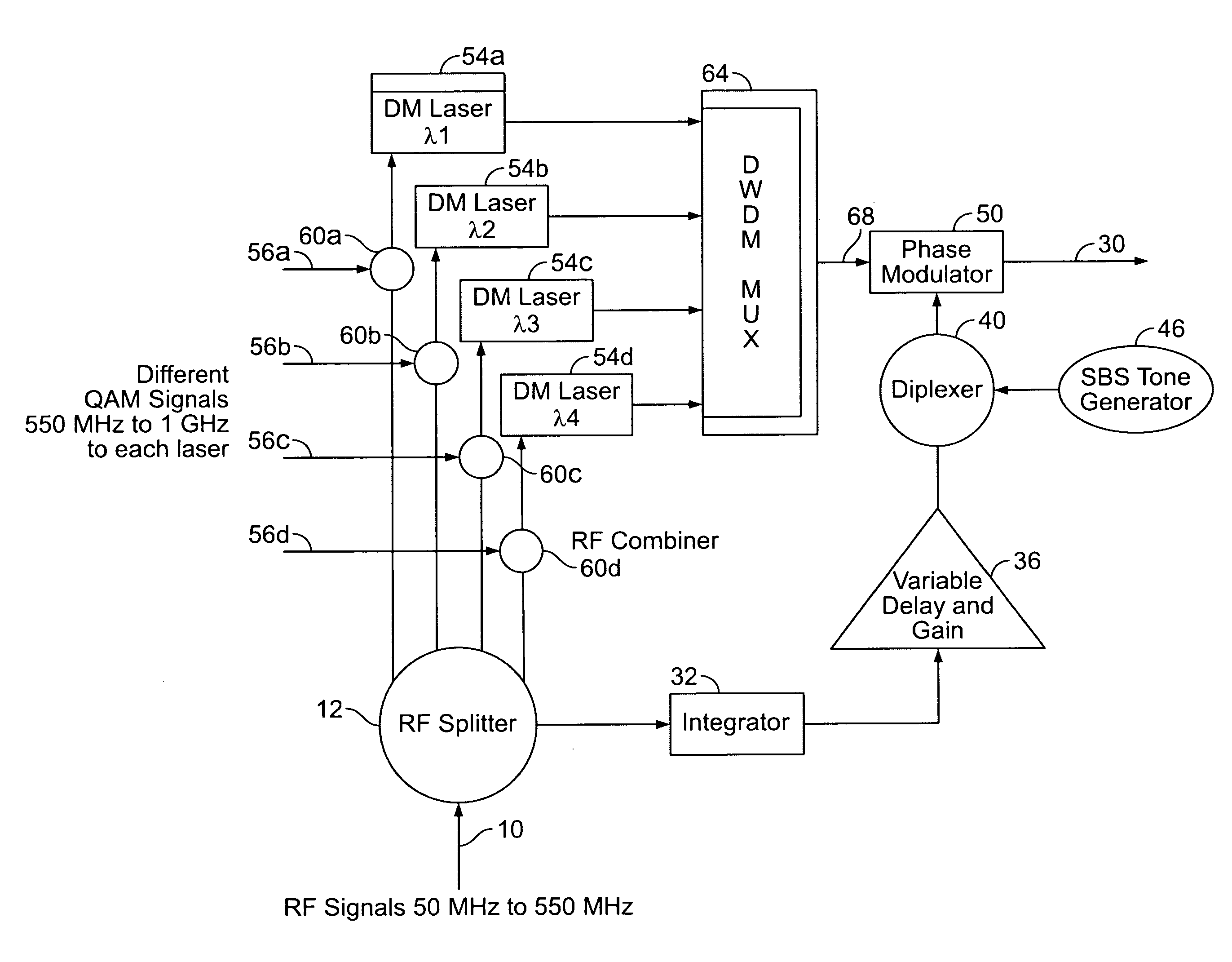
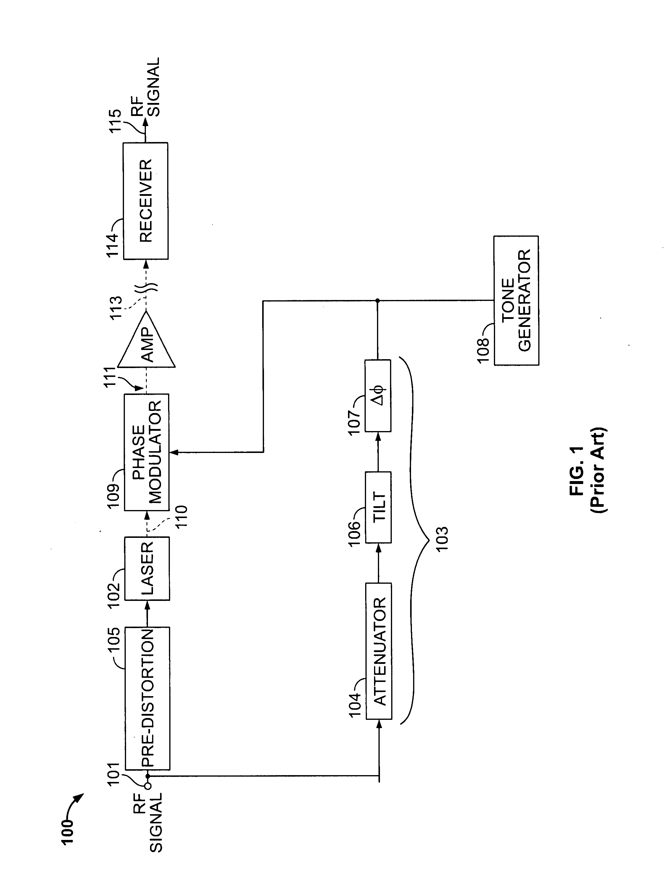
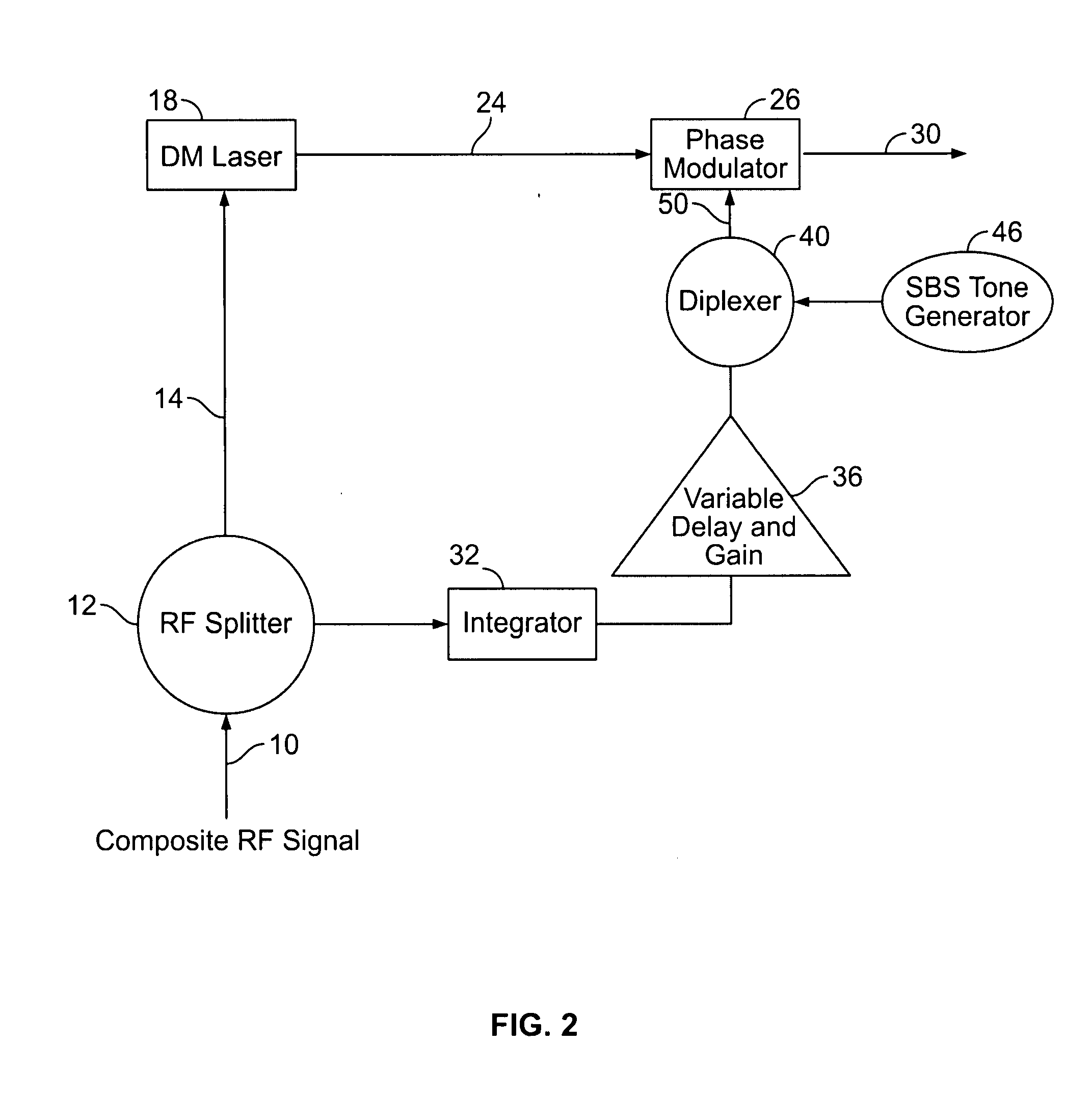
[0016]FIG. 2 shows in a block diagram an optical transmitter in accordance with this disclosure. The various components are each of standard type, commercially available, and well known in the field. The remainder of the system, including the fiber optic span and the optical receiver, are also conventional as in FIG. 1. Hence FIG. 2 (unlike FIG. 1) only shows the transmitter. As shown, there is input terminal 10 to which is applied a composite RF (electrical) signal such as a cable television signal, which may include many channels of analog cable television transmissions or other types of signals, including for instance a QAM signal. The composite RF signal may be an analog video signal or a digital video signal such as QAM (Quadrature Amplitude Modulation). Thus the present apparatus is suitable for use with digital signals also. The input composite RF electrical signal is applied to a radio frequency splitter tap coupler 12 which is a standard device. The RF splitter / RF coupler 1...


PUM


Abstract

A directly modulated optical transmitter for use with a fiber optical communications system operating in the 1550 nm wavelength band exhibits very low chirp. The chirp inherently present in a directly modulated laser is cancelled by a phase modulator which optically modulates the directly modulated laser light beam by applying a 180° phase delay to a split-off portion of the input radio frequency signal. This provides a low cost transmitter capable of operating in the 1550 nm band and with laser chirp effectively cancelled or substantially reduced, thereby avoiding distortions due to laser chirp interactions with the downstream optical fiber.

Description

FIELD OF THE INVENTION[0001]This invention relates to optical transmission systems, for instance those using a laser or laser diode to transmit optical (light) signals over optical fibers and in particular to such a system using a directly modulated laser in the transmitter.DESCRIPTION OF RELATED ART[0002]Directly modulating the analog output signal intensity of a light emitting laser diode (LED) or semiconductor laser or other type of laser with an electrical signal is well known in the field. Typically this is used for transmitting optical analog signals such as voice and video, such as cable television, on optical fibers. Although such analog transmission techniques have the advantage of substantially smaller bandwidth requirements than digital transmission, such as digital pulse code modulation, or analog or pulse frequency modulation, such use of amplitude modulation tends to suffer from noise and nonlinearity of the optical transmitter.[0003]Exemplary types of analog signals t...

Claims


Application Information

Patent Timeline
Patent Type & Authority Applications(United States)
IPC IPC(8): H04J14/00H04B10/18H04B10/43
CPCH04B10/25751H04B10/504H04B10/505H04B10/50597H04B10/506H04B10/58H04B10/2537H04B10/25H04B10/50
Inventor RAMACHANDRAN, MANIGYSEL, HERMANNJASTI, CHANDRA
Owner ATX NETWORKS (TORONTO) CORP
Why Eureka
Try Eureka