

Non-aqueous electrolyte secondary battery
a non-aqueous electrolyte, secondary battery technology, applied in the direction of cell components, final product manufacturing, sustainable manufacturing/processing, etc., can solve the problems of battery reliability not being sufficiently guaranteed, non-aqueous electrolyte batteries have not yet sufficiently satisfied the requirements, short circuits, etc., to achieve small influence, easy formation, and maximize current collection effect
Active Publication Date: 2008-11-06
PANASONIC ENERGY CO LTD
View PDF4 Cites 10 Cited by
- Summary
- Abstract
- Description
- Claims
- Application Information
AI Technical Summary
Benefits of technology
[0020]That said, zirconia or the like may also be used as the inorganic compound other than the above-mentioned substances since the type of the inorganic compound has very small influence on the advantageous effects of the invention.
[0021]The shrinkage prevention layer can also be a porous layer comprising an organic compound. It is particularly desirable that the organic compound comprise at least one substance selected from the group consisting of polyamide, polyimide, and polyamideimide.
[0022]When the shrinkage prevention layer is a porous layer comprising an organic compound, the layer for preventing separator shrinkage can be formed easily as well. It should be noted that polyethylene or the like may be used as the organic compound, other than the above-mentioned substances, since the type of the organic compound has very small influence on the advantageous effects of the invention as in the case of the inorganic compound.
[0023]It is desirable that the positive electrode current collector exposed portion be provided at a region of the positive electrode at which the positive electrode current collector tab is attached, and the negative electrode current collector exposed portion be provided at a region of the negative electrode at which the negative electrode current collector tab is attached.
[0024]In ordinary batteries, each of the current collector tabs (especially the positive electrode current collector tab) is attached to a region where the active material layers is absent so the current collection effect can be maximized. This means that, if the current collector exposed portions are provided separately at different regions from the regions where the current collector tabs are attached, the coating areas of the positive and negative electrode active materials decrease, resulting in a lower battery capacity. Therefore, it is desirable to employ the above-described configuration.
[0025]It is desirable that the ratio of the area of the positive electrode current collector exposed portion to the total area of the positive electrode current collector, the ratio of the area of the negative electrode current collector exposed portion to the total area of the negative electrode current collector, and the ratio of the area of the shrinkage-prevention-layer unformed portion to the total area of the separator each be from 1% to 15%.
Problems solved by technology
However, the non-aqueous electrolyte batteries have not yet sufficiently satisfied the requirements.
Nevertheless, even in the case of using a polyolefin-based separator, if the battery temperature greatly rises above the melting point of the polyolefin, the separator shrinks so that the positive and negative electrode active material layers can come into contact with each other, causing short circuiting.
As a consequence, even when the separator shrinkage at high temperatures is prevented by stacking a heat-resistant microporous film over a surface of the separator, battery reliability cannot be ensured sufficiently as long as the potential of the positive electrode is kept high.
Method used
View moreImage
Smart ImageViewing Examples

Examples
example a
[0034]A non-aqueous electrolyte secondary battery prepared in the manner described in the foregoing preferred embodiment was used for Example A1.
[0035]The battery fabricated in this manner is hereinafter referred to as Battery A of the invention.
Login to View More PUM
| Property | Measurement | Unit |
|---|---|---|
| temperature | aaaaa | aaaaa |
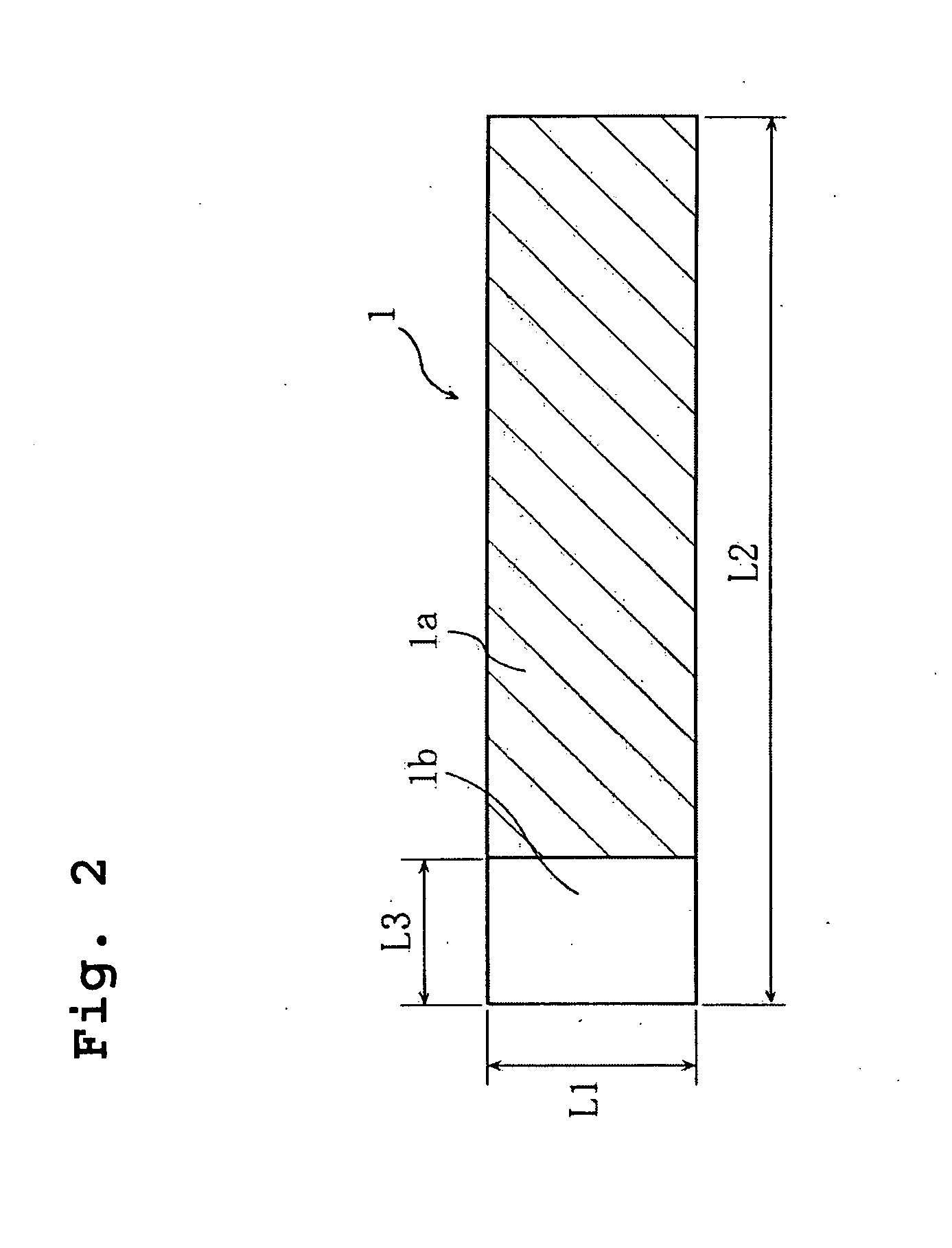
| length L3 | aaaaa | aaaaa |
| length L3 | aaaaa | aaaaa |
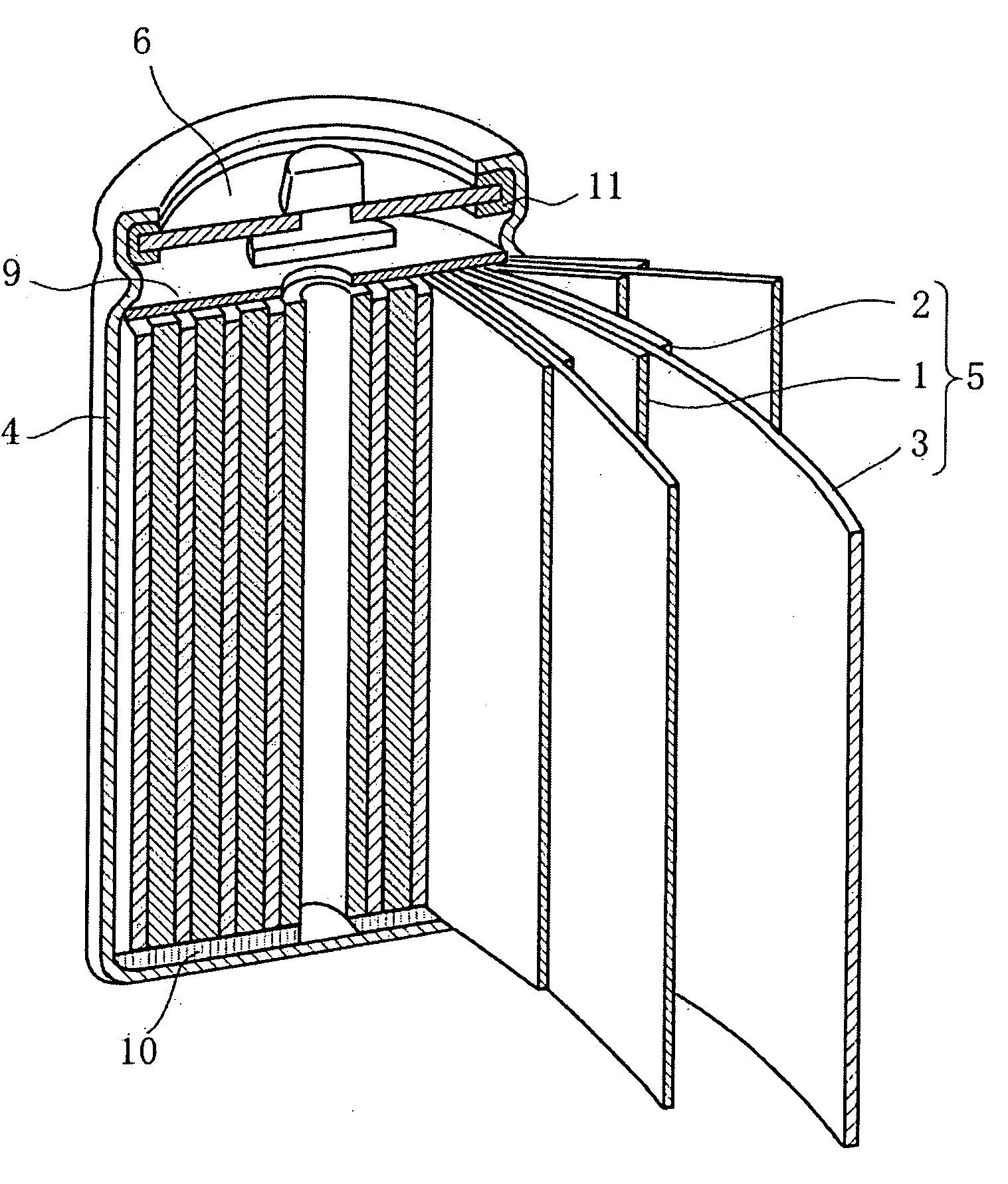
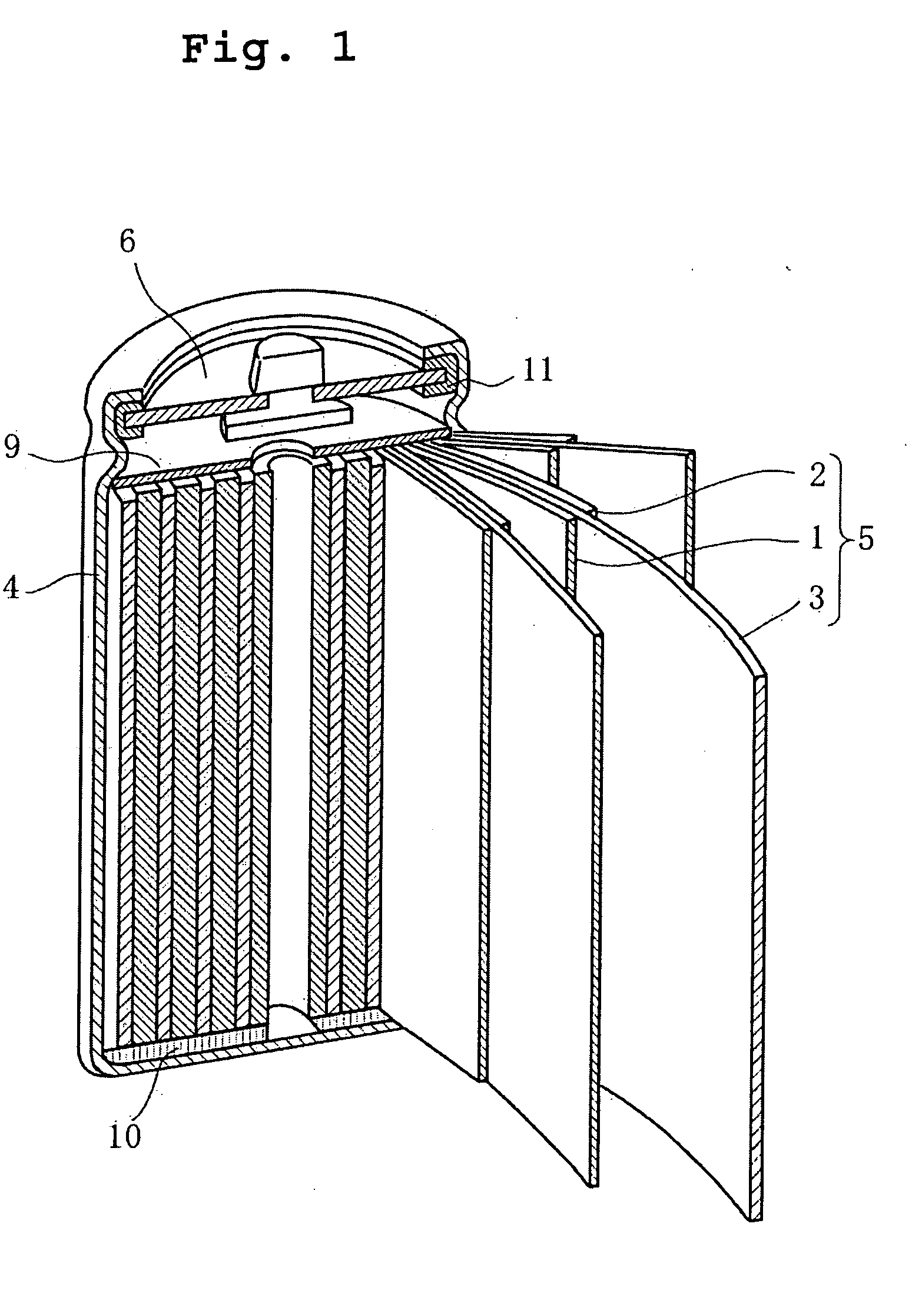
Abstract
A non-aqueous electrolyte secondary battery is provided that remarkably improves battery reliability by quickly lowering the potential of the positive electrode while preventing separator shrinkage at high temperatures. A separator has on its surface a shrinkage-prevention-layer formed portion (3a), in which a layer for preventing separator shrinkage is formed, and a shrinkage-prevention-layer unformed portion (3b), in which the layer for preventing separator shrinkage is not formed. A positive electrode current collector and a negative electrode current collector respectively have a positive electrode current collector exposed portion (1b) and a negative electrode current collector exposed portion (2b). The shrinkage-prevention-layer unformed portion (3b) of the separator is disposed at a region where the current collector exposed portions (1b, 2b) face each other.
Description
BACKGROUND OF THE INVENTION[0001]1. Field of the Invention[0002]The present invention relates to improvements in lithium-ion batteries or non-aqueous electrolyte secondary batteries such as polymer batteries. More specifically, the invention relates to a battery structure that is capable of stabilizing a non-aqueous electrolyte secondary battery quickly even when the non-aqueous electrolyte secondary battery develops an abnormal condition for some reason, whereby high reliability can be achieved even with a high capacity, high power battery construction.[0003]2. Description of Related Art[0004]Mobile information terminal devices such as mobile telephones, notebook computers, and PDAs have become smaller and lighter at a rapid pace in recent years. This has led to a demand for higher capacity batteries as the drive power source for the mobile information terminal devices. With their high energy density and high capacity, non-aqueous electrolyte batteries that perform charge and disch...
Claims
Login to View More Application Information
Patent Timeline
 Patent Type & AuthorityApplications(United States)
IPC IPC(8): H01M2/16H01M4/13H01M10/0587H01M50/417H01M50/443
CPCH01M2/164Y02E60/122H01M2/166H01M2/1653Y02E60/10H01M50/446Y02P70/50H01M50/417H01M50/443
InventorBABA, YASUNORIIMACHI, NAOKIOGASAWARA, TAKESHI
OwnerPANASONIC ENERGY CO LTD