Particulate Filter Regeneration and NOx Catalyst Re-Activation

a technology of nox catalyst and reactivation, which is applied in the direction of electric control, machines/engines, mechanical equipment, etc., can solve the problems of nox catalyst deactivation, poor performance of dpf regeneration, and potential disadvantages of such an approach, and achieve the effect of improving performance on subsequent engine starts

Inactive Publication Date: 2008-11-13
FORD GLOBAL TECH LLC
View PDF0 Cites 64 Cited by
  • Summary
  • Abstract
  • Description
  • Claims
  • Application Information

AI Technical Summary

Benefits of technology

[0005]In one approach, the above issues may be at least partially addressed by, after lean DPF regeneration, providing a rich or intermittently rich exhaust air-fuel ratio for a duration lasting until NOx catalyst temperature falls to a minimum threshold. Such operation may be used to reactivate NOx catalysts and reverse the deactivation that may have occurred from the high temperature lean operation associated with the previous DPF regeneration. In one particular example, such operation may be provided in response to an engine shut-down during DPF regeneration, thereby enabling improved performance on subsequent engine starts.

Problems solved by technology

However, the inventors herein have recognized a potential disadvantage with such an approach.
In particular, catalyst deactivation of the NOx catalyst may occur during the high temperature lean operation of DPF regeneration.
Further, the rich operation for sulfur reduction occurring during the high temperature DPF regeneration may not last for sufficient duration (or may not be rich enough) to reactivate the NOx catalyst.
Thus, NOx performance may degrade even though the sulfur has been removed, as the NOx catalyst may be made substantially inactive due to high temperature lean operation, separate and apart from, sulfur accumulation.

Method used


Image

  • Particulate Filter Regeneration and NOx Catalyst Re-Activation
  • Particulate Filter Regeneration and NOx Catalyst Re-Activation
  • Particulate Filter Regeneration and NOx Catalyst Re-Activation

Examples


Embodiment Construction

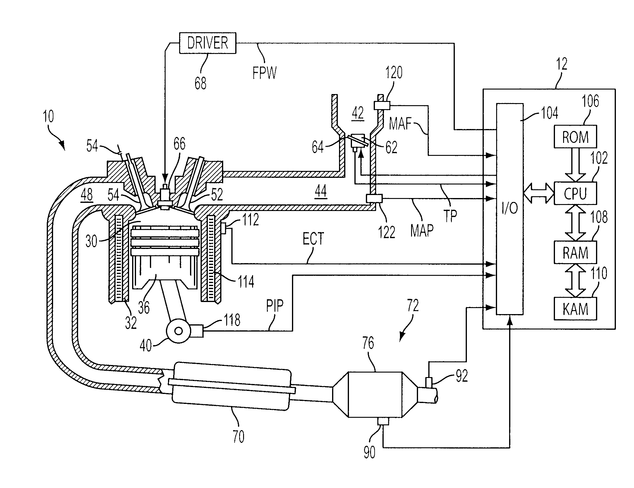
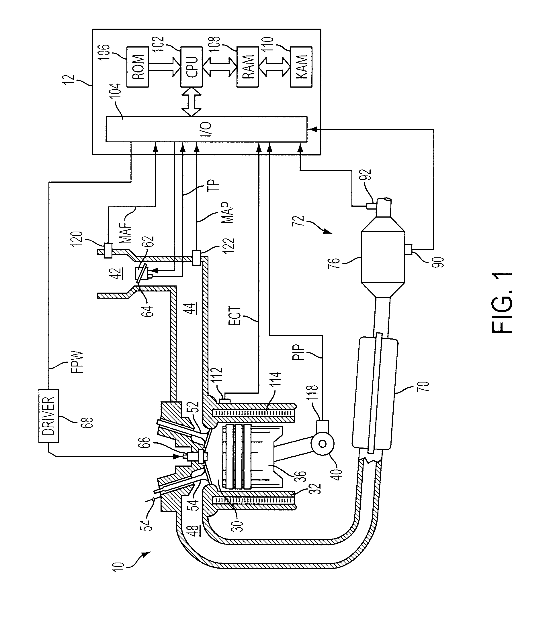
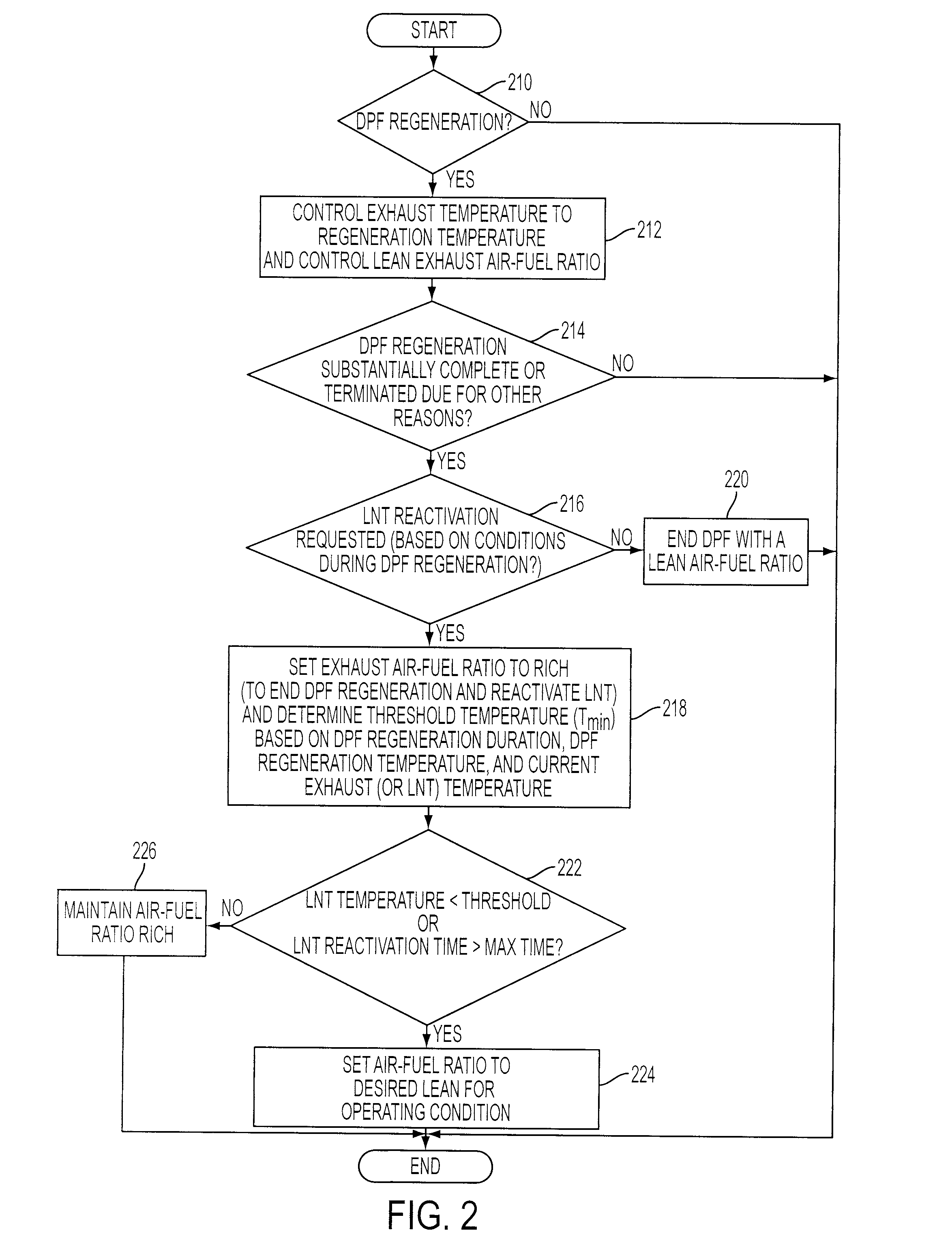
[0010]As described in further detail herein, there may be various issues encountered when concluding, or exiting, a DPF regeneration process. One strategy to address at least some of these issues switches the exhaust gas composition from primarily lean (which was used during the DPF regeneration to provide excess oxygen to support the particulate removal) to primarily rich to thereby expose other emission control devices, such as a LNT, to rich exhaust gases for a brief duration while still at high temperatures. Such operation may enable the restoration of catalytic materials in the LNT (for example, platinum (Pt) and rhodium (Rh)) to a reduced state with enhanced NOx control capability. This approach is generally in contrast to previous approaches in which DPF regeneration is terminated under high-temperature predominantly lean conditions, and such lean conditions are continued which may leave the LNT catalyst in a relatively inactive state. However, various additional features may...


PUM


Abstract

A system and method may be provided for operating a system having an engine with an emission control system, the emission control system including a lean NOx trap and a particulate filter, where after lean exhaust gas air-fuel ratio regeneration of the particulate filter at an elevated regeneration temperature, a rich or intermittently rich exhaust air-fuel ratio is provided for a duration lasting until LNT temperature falls to a minimum threshold, where said rich or intermittently rich operation reactivates catalysts in the LNT and reverses deactivation caused by the elevated temperature lean operation associated with previous particulate filter regeneration.

Description

FIELD[0001]This present application relates to an emission control system of an internal combustion engine, and in particular those combining particulate filtering systems with lean NOx traps.BACKGROUND AND SUMMARY[0002]Engine systems may use a diesel particulate filter (DPF) to reduce particulate emissions. In the case of an active DPF, deliberate changes to vehicle operation may be used to regenerate the filter, and may be triggered when the particulate matter builds up to levels where pressure drop across the filter exceeds a specified level. Active regeneration of a loaded DPF can take several tens of minutes and may require that the exhaust gas supplied to the DPF has a considerable excess of oxygen (over reductants) to ensure sufficient oxygen to sustain combustion of the particulate matter. Engine systems may also include lean NOx traps (LNT) used to control NOx emissions. Lean NOx traps may also variously be referred to as NOx storage-reduction catalysts, or simply NOx catal...

Claims


Application Information

Patent Timeline
Patent Type & Authority Applications(United States)
IPC IPC(8): F01N3/36
CPCF01N3/0821F01N2570/14F02D41/0235F02D41/0275F02D41/029F02D41/042F02D2041/0265Y02T10/20Y02T10/12Y02A50/20F01N3/0871
Inventor MCCABE, ROBERT WALTERXU, LIFENGHOARD, JOHN WILLIAMADAMS, KAREN MARIE
Owner FORD GLOBAL TECH LLC
Why Eureka
Try Eureka