
Method and system for porous flame holder for hydrogen and syngas combustion

a technology of hydrogen and syngas, which is applied in the direction of combustion types, machines/engines, lighting and heating apparatus, etc., can solve the problems of affecting the performance of the nozzle assembly, the inability to use prior art designs applicable only to burning natural gas fuels,

Inactive Publication Date: 2008-11-13
GENERAL ELECTRIC CO
View PDF23 Cites 12 Cited by
  • Summary
  • Abstract
  • Description
  • Claims
  • Application Information

AI Technical Summary

Benefits of technology

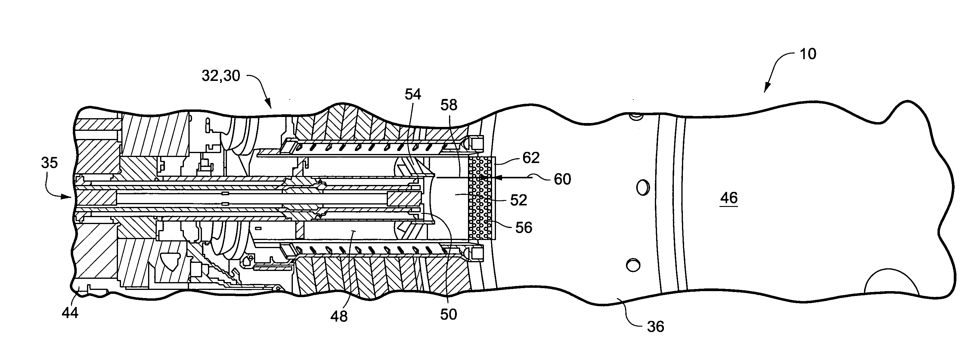
[0008]A method is disclosed for modifying the mixing region of a natural gas nozzle assembly to a syngas or hydrogen nozzle assembly, the method includes: placing a porous flame stabilizer a distal end of an air tube of the nozzle assembly, and allowing fuel and air from the nozzle assembly through the flame stabilizer before the mixture is burnt in a combustion zone. The method may further include selecting the porous flame stabilizer in such a way that it creates the necessary pressure drop between a combustion zone immediately downstream of the flame stabilizer and an air fuel mixture in the air tube and immediately upstream of the flame stabilizer, wherein the required pressure drop is sufficient to prevent propagation of flame through the flame stabilizer. Higher pressure drops in the porous structure results in increased fuel-air mixture velocities for stabilizing the high flame speeds of H2 / syngas fuels.

Problems solved by technology

Less forgiving properties of hydrogen (H2) and syngas fuels such as higher flame speeds, lower ignition times makes it impossible to use prior art designs applicable only for burning natural gas fuels.
Flame holding in the unburnt mixing region has the potential to damage the components of the nozzle assembly.

Method used


Image

  • Method and system for porous flame holder for hydrogen and syngas combustion
  • Method and system for porous flame holder for hydrogen and syngas combustion
  • Method and system for porous flame holder for hydrogen and syngas combustion

Examples


Embodiment Construction

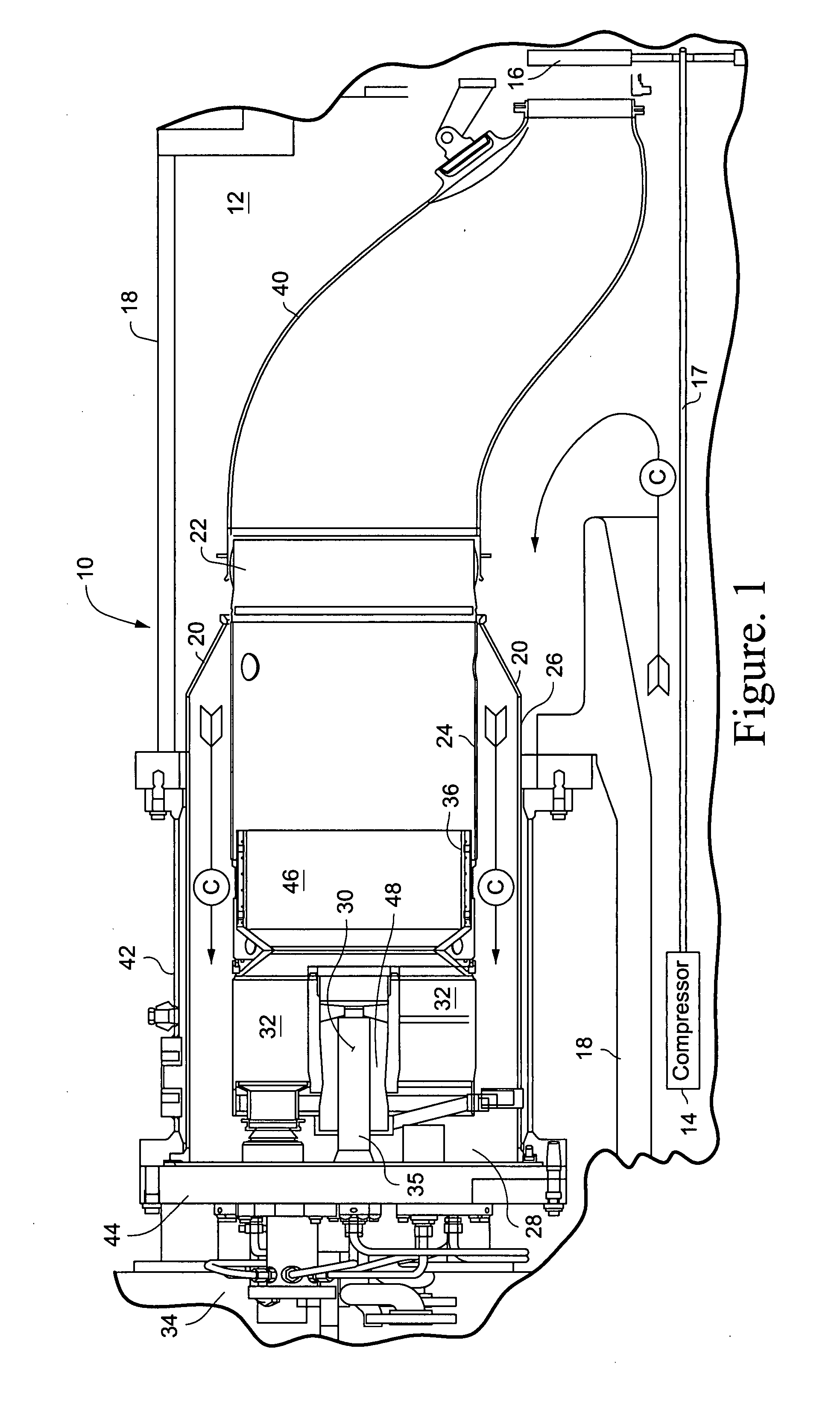
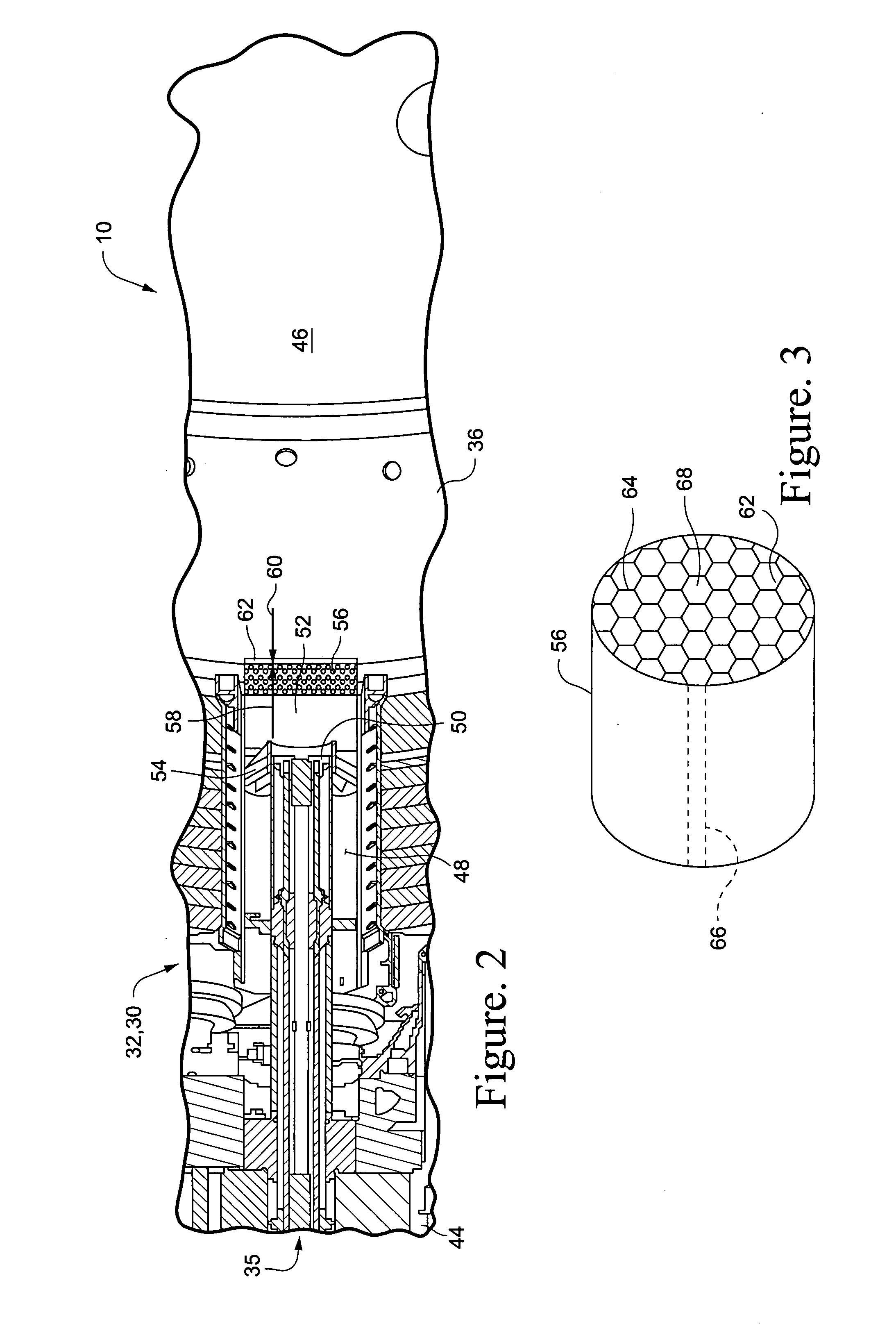
[0012]A porous flame stabilizer has been developed for insertion into a mixing region of a fuel nozzle assembly of a combustor for an industrial gas turbine. The flame stabilizer has a high porosity to allow sufficient amount of fuel and air mixture to flow through the media at a higher velocity and design pressure drops. The porous structure prevents the propagation of flame upstream in to the structure and the mixing region. The propagation of flame is prevented by allowing higher mixture velocities in the porous structure and the structure can itself act like an arrestor to the flame. The porous structure may include a thermal barrier coating (TBC) on a downstream region of the structure. The TBC shields the porous structure from being exposed to flame residing downstream of the structure.

[0013]FIG. 1 shows a combustor 10, in partial cross-section, for a gas turbine 12 having a compressor 14 (partially shown), a plurality of combustors 10 (one shown), and a turbine represented he...


PUM


Abstract

A mixing region of a fuel nozzle assembly for a combustor in a gas turbine, the assembly including: a gaseous fuel nozzle having a center axis and extending along the center axis, the fuel nozzle including a gaseous fuel passage and a fuel nozzle at a distal end of the passage; an air tube concentric with the fuel nozzle and defining an air passage between the air tube and the fuel nozzle, wherein the air tube includes a distal section extending axially beyond the fuel injection nozzle; a first fuel-air mixing zone defined by and inside the distal section of the air tube, wherein said first fuel-air mixing zone is downstream of the fuel injection nozzle; a flame holder comprising a porous structure with thermal barrier coating and micro swirlers and defining a downstream end of the first fuel-air mixing zone, wherein fuel and air from the first fuel-air mixing zone pass through the porous structure of the flame holder and into a combustion zone of the combustor.

Description

BACKGROUND OF THE INVENTION[0001]This invention relates to the mixing region of the fuel nozzle assembly for a combustor in a gas turbine burning on Syngas or hydrogen fuels. Less forgiving properties of hydrogen (H2) and syngas fuels such as higher flame speeds, lower ignition times makes it impossible to use prior art designs applicable only for burning natural gas fuels.[0002]Industrial gas turbines have a combustion section typically formed by an array of can-annular combustors. Each combustor includes a fuel nozzle mixing region that provides specified amounts of fuel-air mixture to a combustion zone within the combustor. The fuel-air mixture is allowed to burn inside the combustion zone to generate hot, pressurized combustion gases that drive a turbine.[0003]Natural gas, e.g., primarily methane, is a common fuel for industrial gas turbines. Rapid depletion of hydrocarbon resources has led to an increased focus on using coal derived H2 and / or syngas for industrial gas turbines....

Claims


Application Information

Patent Timeline
IPC IPC(8): F23R3/32
CPCF23C2900/9901F23D14/70F23D14/74F23R2900/00002F23D2203/104F23R3/286F23D14/82
Inventor POYYAPAKKAM, MADHAVAN
Owner GENERAL ELECTRIC CO
Learn More