Handheld work apparatus

a work apparatus and hand-held technology, applied in the direction of manufacturing tools, machines/engines, portable power-driven tools, etc., can solve the problem of increasing the total weight of the saw, and achieve the effect of reducing the effective gyroscopic force, reducing the weight of the work apparatus, and good balance of inertial forces

Inactive Publication Date: 2008-11-13
ANDREAS STIHL AG & CO KG
View PDF5 Cites 4 Cited by
  • Summary
  • Abstract
  • Description
  • Claims
  • Application Information

AI Technical Summary

Benefits of technology

[0009]A simple opposite drive of the components of the second component group can be achieved when the work tool is driven by the internal combustion engine via a belt with the belt running crossed over. The crossed over course of the belt makes possible a drive in mutually opposite directions without additional components and therefore without increasing the weight of the work apparatus. It can, however, be provided that the work tool is driven via a gear assembly by the crankshaft. The gear assembly is then especially a sprocket wheel transmission. It can, however, also be provided that the transmission is a planetary transmission. A planetary transmission makes possible the same axis arrangement of drive axis and output axis on the transmission. Different transmission ratios can be achieved with a sprocket wheel transmission as well as with a planetary transmission. Different transmission ratios make possible a good balance of inertial forces for differently large rotating masses. By selecting a suitable transmission ratio, the effective gyroscopic forces can be additionally reduced.
[0010]The crankshaft is connected to the work tool via a clutch. The clutch makes possible a simple start of the work apparatus because the work tool is not yet connected to the crankshaft during the start operation. Advantageously, the clutch is driven in a first rotational direction and the first component assembly is formed by crankshaft, flywheel and the clutch. Additional inertial forces such as balancing weights and the like are not provided. In order to further reduce inertial forces during operation, it can, however, also be provided that the clutch is driven in the second rotational direction and that the first component group is formed of the crankshaft and the flywheel. In this way, a good compensation of the inertial forces is made possible in that the work tool as well as the clutch are driven in the direction opposite to the crankshaft and the flywheel. It can, however, also be provided that the flywheel is driven in a direction opposite to the crankshaft in order to reduce gyroscopic forces arising during operation. Especially, the first component assembly includes the work tool and the second component assembly includes a flywheel. The second component assembly is driven in a second rotational direction opposite to the first rotational direction.

Problems solved by technology

However, the total weight of the saw is increased by the additional balance masses and this is disturbing in handheld work apparatus and especially in portable handheld work apparatus.

Method used


Image

  • Handheld work apparatus
  • Handheld work apparatus
  • Handheld work apparatus

Examples


Embodiment Construction

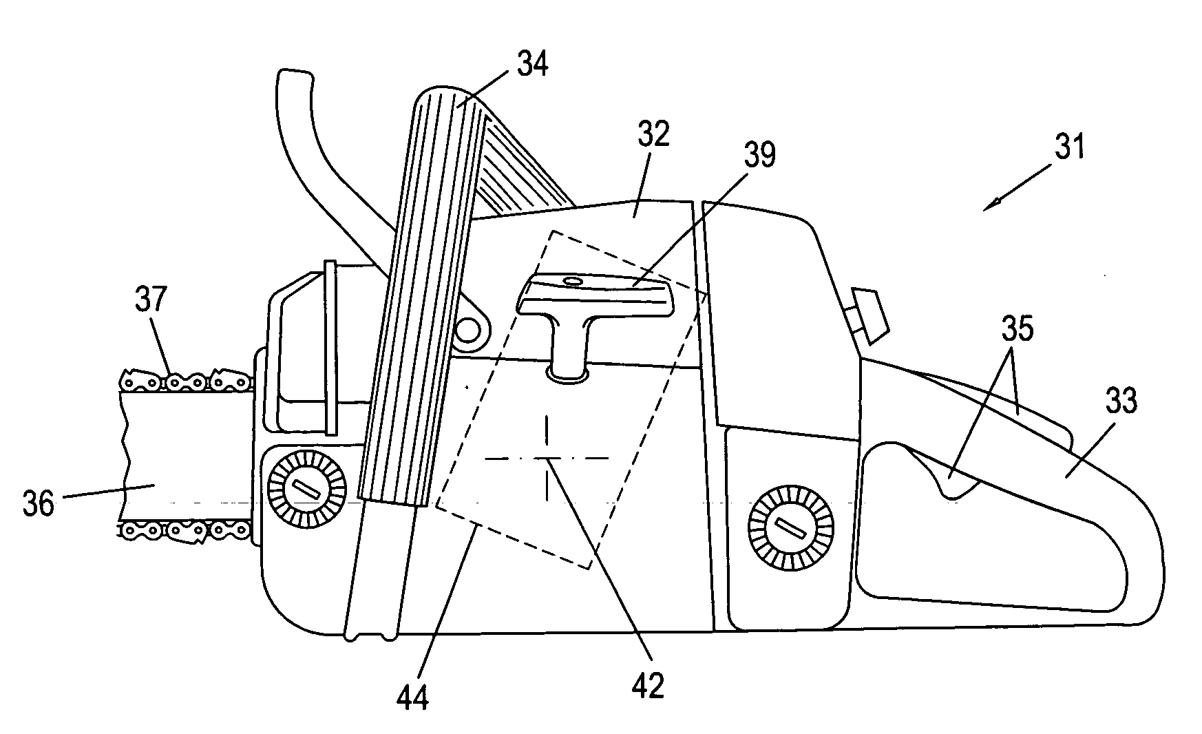
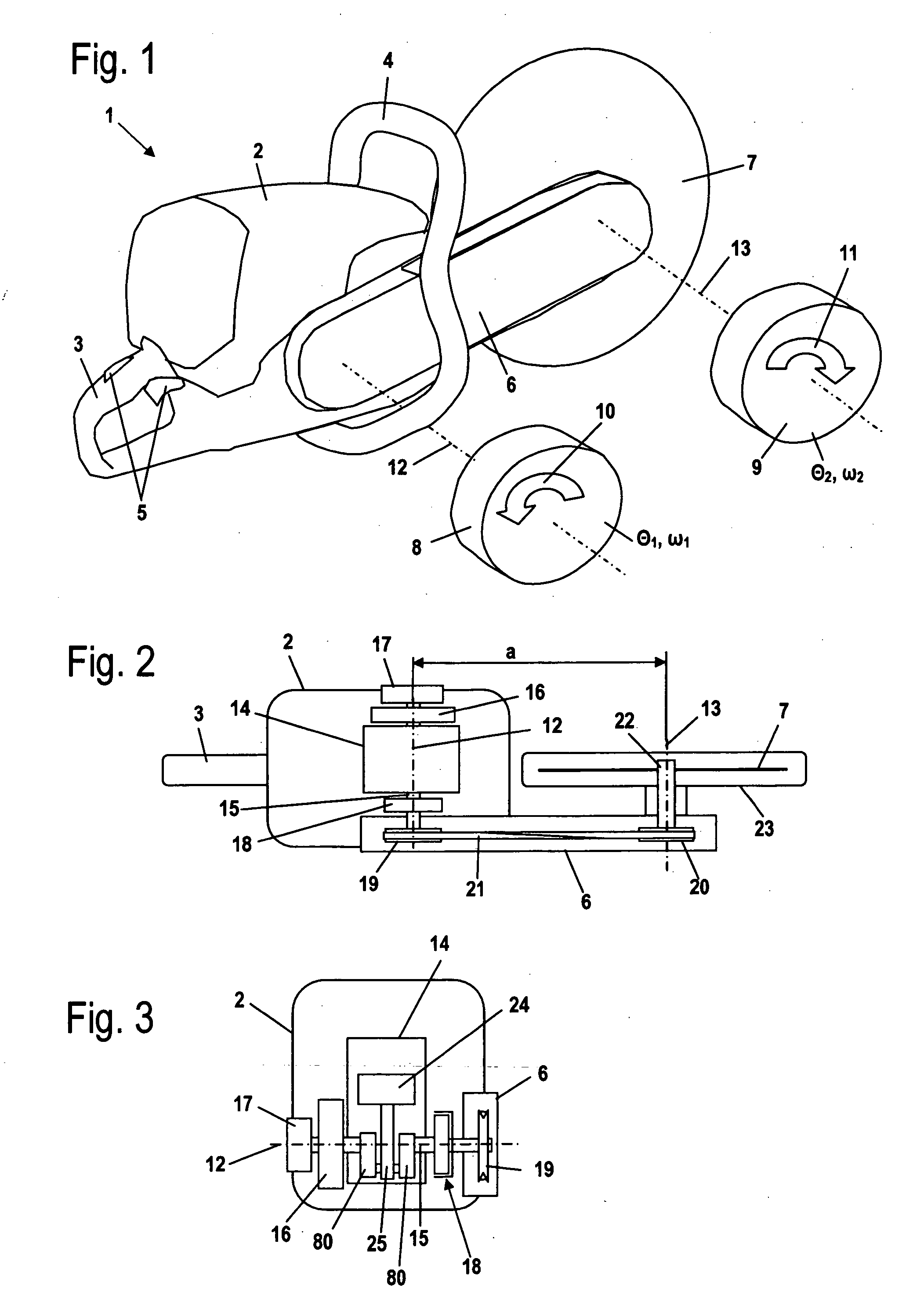
[0021]FIG. 1 shows a portable handheld work apparatus in the form of a cutoff machine 1. The cutoff machine 1 has a housing 2 on which a rearward handle 3 and a tubular handle 4 for guiding the cutoff machine 1 are mounted. Operator-controlled elements 5 are attached to the rearward handle 3 and, in the embodiment, include a throttle lever as well as a throttle lever lock. Also, further or other operator-controlled elements can be provided.

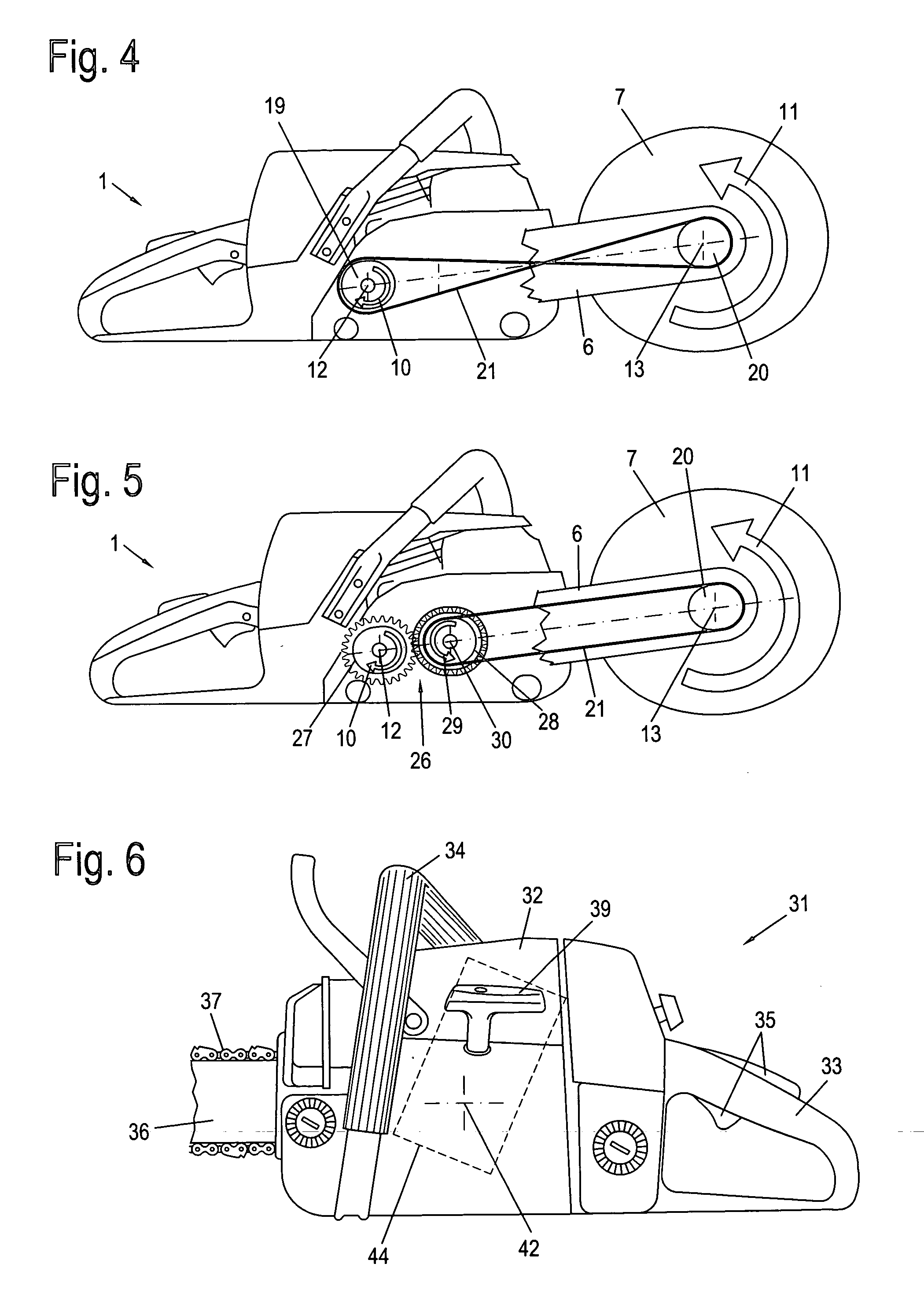
[0022]An outrigger 6 is mounted on the housing 2 and extends forwardly, that is, on an end of the housing 2 facing away from the rearward handle 3. A cutoff disc 7 is supported on the outrigger 6. The cutoff disc 7 is rotationally driven about a second rotational axis 13.

[0023]An internal combustion engine 14 is mounted in the housing 2 of the cutoff machine 1 for driving the cutoff disc 7. The engine is shown schematically in FIGS. 2 and 3. As shown in FIG. 3, the internal combustion engine includes a piston 24 which rotatably drives a crankshaft...


PUM


Abstract

A handheld work apparatus has an internal combustion engine (14, 44, 94) which has a crankshaft (15, 45, 95) which, in turn, drives a work tool of the work apparatus. The work apparatus has a first component group which includes the crankshaft (15, 45, 95) and which is driven in a first rotational direction (10, 40, 70, 90). In order to hold the gyroscopic forces low which act during operation, the work apparatus has a second component group which includes the work tool and which is driven in a second rotational direction (11, 41, 71, 91) opposite to the first rotational direction (10, 40, 70, 90).

Description

CROSS REFERENCE TO RELATED APPLICATION[0001]This application claims priority of German patent application no. 10 2007 020 368.5, filed Apr. 30, 2007, the entire content of which is incorporated herein by reference.FIELD OF THE INVENTION[0002]The invention relates to a handheld work apparatus and especially to a portable handheld work apparatus such as a motor-driven chain saw, cutoff machine, blower apparatus or the like.BACKGROUND OF THE INVENTION[0003]German patent publication 2,201,068 discloses a portable motor-driven chain saw wherein the inertial forces of the first order, which develop in the internal combustion engine, are compensated by balancing weights. The balance weights are driven opposite to the crankshaft by a sprocket wheel transmission. However, the total weight of the saw is increased by the additional balance masses and this is disturbing in handheld work apparatus and especially in portable handheld work apparatus.SUMMARY OF THE INVENTION[0004]It is an object of...

Claims


Application Information

Patent Timeline
Patent Type & Authority Applications(United States)
IPC IPC(8): F02B63/02
CPCB25F5/001
Inventor PESIK, LUBOMIRMENZEL, JOHANNESSTEINMAIER, JURGENERATH, JURGEN
Owner ANDREAS STIHL AG & CO KG
Why Eureka
Try Eureka