Power supplies for RF power amplifier

a power amplifier and power supply technology, applied in the direction of electric variable regulation, process and machine control, instruments, etc., can solve the problems of poor efficiency of small transmission power levels, low transmission power levels, and tight control of frequency and group delay respons

Active Publication Date: 2008-11-13
NOKIA TECHNOLOGLES OY
View PDF18 Cites 160 Cited by
  • Summary
  • Abstract
  • Description
  • Claims
  • Application Information

AI Technical Summary

Benefits of technology

[0027]controlling the buck-type switched-mode power supply to operate at a higher switching frequency, when the power amplifier operates in an envelope elimination and restoration (EER) mode or in an envelope tracking (ET) mode, and to operate at a lower switching frequency, when the power amplifier operates in a linear mode.
[0028]Still another aspect of the invention is a computer program embodied on a computer readable medium, said computer program comprising a program code for controlling a processor to execute control methods according to various embodiments of the invention.
[0029]Still another aspect of the invention is a controller comprising means for embodying control methods according to various embodiments of the invention.

Problems solved by technology

With this approach, the needed output transmission power can be easily obtained from the PA, but the efficiency for small transmission power levels is poor.
If the two converters are cascaded, the efficiency at low transmission power levels suffers from the cascaded converters and the high voltage between them.
However, in applications that use the envelope elimination and restoration (EER) technique, a very tightly controlled frequency and group delay response is needed.
With a Buck-Boost switching-mode power supply, the output voltage range where the mode changes is quite critical, and distortion occurs.
Also, in the Boost mode of operation it is difficult to keep the response unaffected.
The problems regarding efficiency are becoming more significant with the battery technology, e.g. lithium battery technology, lowering the cut of voltage from the present range, e.g. 3V, to about 2.5V or lower.
As a consequence, a transmission (TX) power amplifier becomes very inefficient and variation in its performance increases, if it is designed for 2.3V supply voltage, for example.

Method used


Image

  • Power supplies for RF power amplifier
  • Power supplies for RF power amplifier
  • Power supplies for RF power amplifier

Examples


Embodiment Construction

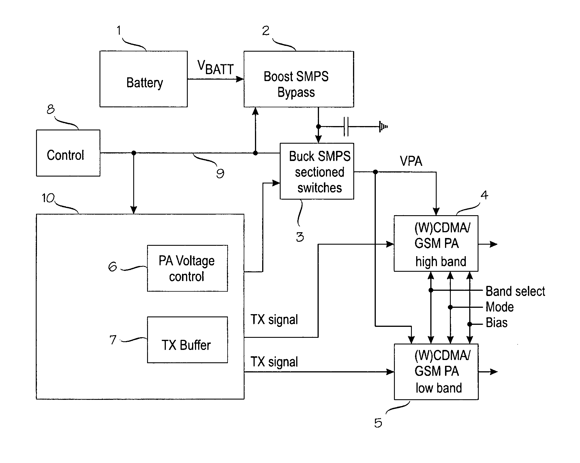
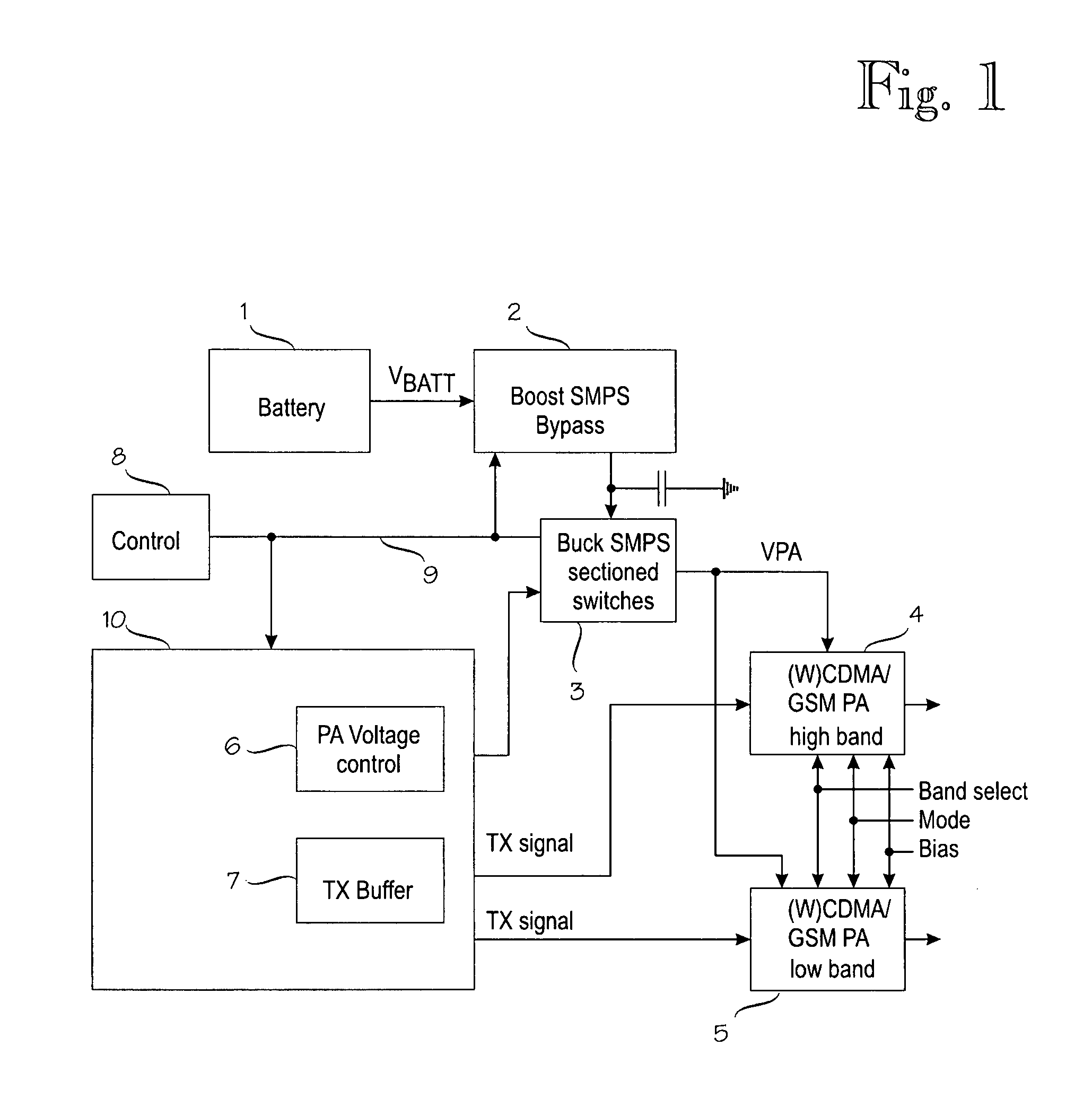
[0036]Referring to FIG. 1, a block diagram of an exemplary RF transmitter (TX) circuitry is shown in which a supply voltage is provided from a battery 1 to power amplifiers (PA) 4, 5 through cascaded Boost and Buck switched-mode power supplies (SMPS) 2, 3.

[0037]A battery 1 provides a battery voltage Vbatt to a Boost-type switched mode power supply 2 according to an embodiment of the invention. The battery may be any type of battery suitable for portable devices, such as a lithium cell battery or a nickel cadmium battery. The battery voltage Vbatt may have any low voltage value depending on the application and the battery technology selected. A typical battery voltage may be about 3 Volts or lower, or even 2.5 Volts or lower.

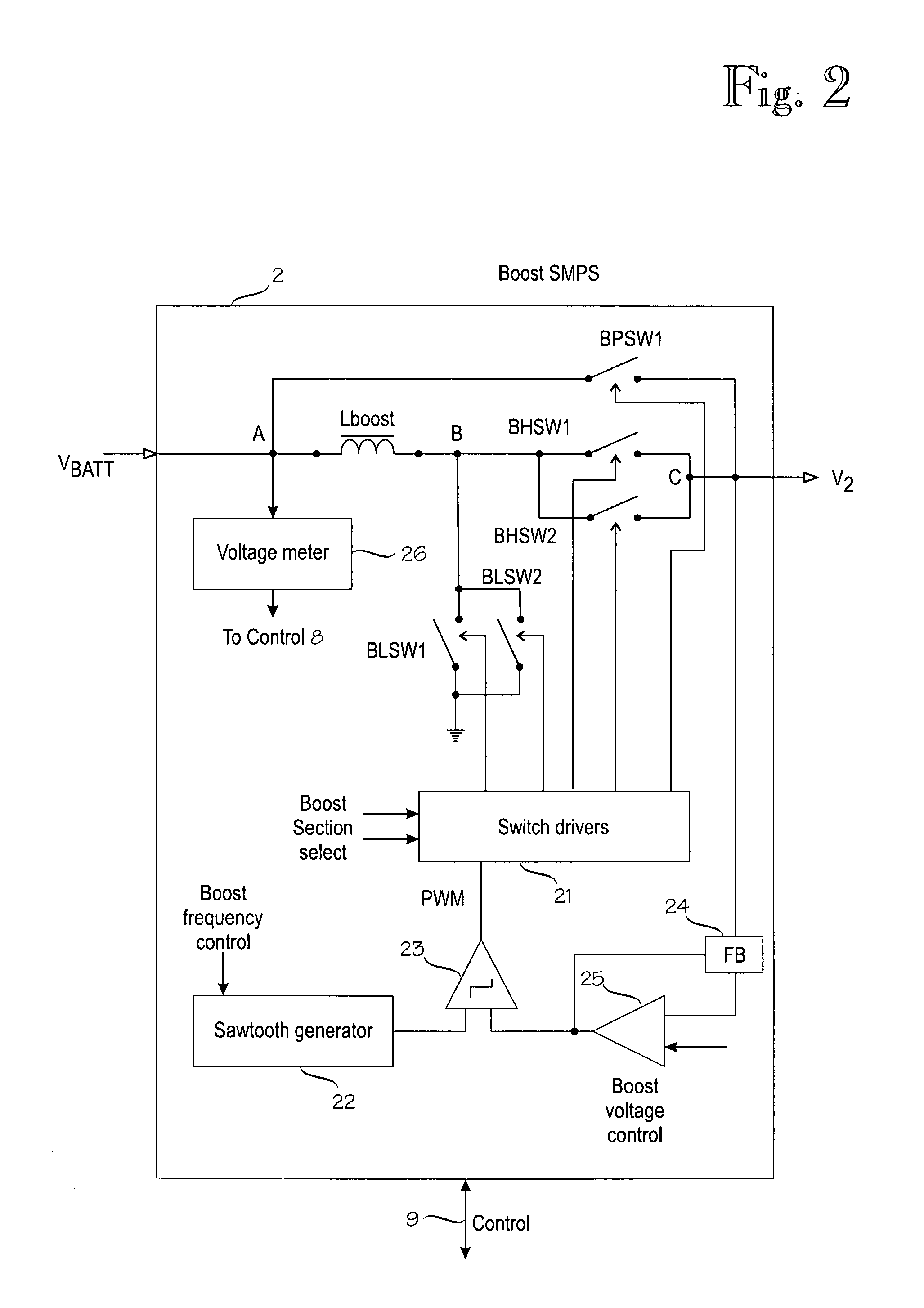
[0038]The Boost switched-mode power supply 2 up-converts from the battery voltage Vbatt a supply voltage V2 with a raised voltage level to a Buck-type switched-mode power supply 3. The Boost switched-mode power supply may also include a bypass function that bypas...


PUM


Abstract

Switched-mode power supplies (SMPSs) and their control methods for radio frequency (RF) power amplifiers in battery-powered wireless transmitter devices involve a Boost-type SMPS and a Buck-type SMPS in cascade connection which are controlled so that high efficiency is maintained for various loads and transmission power levels. The Boost SMPS and the Buck SMPS can be controlled based on the mode of operation of the transmitter, such as the actual battery voltage, the needed output power, the selected frequency band, the selected RF power amplifier (PA), the selected modulation method of the transmission signal, and/or the selected PA voltage control method, such as the envelope elimination and restoration (EER) technique, the envelope tracking (ET) technique, or the power-level tracking (PT) technique.

Description

FIELD OF THE INVENTION[0001]The present invention relates to switched-mode power supplies, and more specifically to switched-mode power supplies and their control methods for radio frequency (RF) power amplifiers in battery-powered wireless transmitter devices.BACKGROUND OF THE INVENTION[0002]Energy-efficient radio frequency (RF) power amplifiers (PA) are critical components in mobile, battery-operated wireless communication devices, e.g. mobile phones, personal digital assistants (PDA), etc., because they determine a significant portion of the total power consumption of such devices. Batteries with low supply voltage, typically about 3V, are employed in the portable devices. It has been possible to design a PA for the 3V battery voltage even if the efficiency already has dropped a bit. In order to get high efficiency from a PA, a switching-mode power supply (SMPS), often referred to as a Boost converter or a step-up converter is needed to up-convert the battery voltage to a value h...

Claims


Application Information

Patent Timeline
Patent Type & Authority Applications(United States)
IPC IPC(8): G05F5/00
CPCH02M3/1584H03F3/21H03F1/0211H02M3/156H02M3/158H02M3/1582H02J2207/20H02M1/007
Inventor MURTOJARVI, SIMO
Owner NOKIA TECHNOLOGLES OY
Why Eureka
Try Eureka