Fluid Dynamic Bearing Mechanism

a dynamic bearing and bearing mechanism technology, applied in sliding contact bearings, instruments, record information storage, etc., can solve the problems of small shaft torque loss and lower power consumption, and achieve the effect of reducing shaft torque loss, improving rotation accuracy, and reducing power consumption

Inactive Publication Date: 2008-11-13
MINEBEA CO LTD
View PDF5 Cites 12 Cited by
  • Summary
  • Abstract
  • Description
  • Claims
  • Application Information

AI Technical Summary

Benefits of technology

[0013]The present invention aims to resolve the problems of the conventional fluid dynamic bearing mechanisms and to provide a fluid dynamic bearing mechanism (or alternatively a fluid dynamic bearing system), for applications such as hard disk drives, that stabilizes the rotation of the rotating shaft and further improve the accuracy of rotation, along with decreasing the shaft torque loss as much as possible, and cutting down on the consumption of power, while using a relatively simple setup to ensure bearing rigidity.
[0014]The fluid dynamic bearing mechanism of the present invention includes a cylindrical bearing case with a cylindrical hole at its center, an end plate that seals one end of said bearing case, a shaft that has at least one part inserted into and supported by the bearing housing formed by the bearing case and the end plate. The cylindrical hole of the bearing case has a large diameter part and a small diameter part. The shaft is a stepped shaft having a large diameter part and a small diameter part that respectively face the large diameter part and the small diameter part of the stepped cylindrical hole. A first dynamic pressure generating groove is formed on either the large diameter part of the stepped cylindrical hole or the outer circumferential surface of the large diameter part of the stepped shaft. A second dynamic pressure generating groove is formed on either the small diameter part of the stepped cylindrical hole or the outer circumferential surface of the small diameter of the stepped shaft. A third dynamic pressure generating groove is formed on an inner surface of the end plate or a bottom surface of the stepped shaft. Additionally, dynamic pressure generating groove can also be formed, preferably on either a step part, or alternatively, on a tapered part of the stepped cylindrical hole or the surface of a step part or a tapered part of the stepped shaft. Small gaps faced by each of the first dynamic pressure generating groove, the second dynamic pressure generating groove and the third dynamic pressure generating groove are filled with dynamic pressure generating lubricating oil. Another embodiment of the fluid dynamic bearing mechanism also includes a thrust ring. The bearing case in this embodiment has an expanded diameter part wherein the thrust ring is fitted. A dynamic pressure generating groove may also be formed on a step surface of the expanded diameter or an upper surface of the thrust ring. Another location for a dynamic pressure generating groove can be the upper surface of the endplate or a bottom surface of the thrust ring. Another embodiment of the fluid dynamic bearing mechanism can also include an annular ring that straddles the stepped shaft and the stepped cylindrical hole and prevents the shaft from coming out of the hole. The various embodiments of the fluid dynamic bearing mechanism can also include a slight local expansion of the diameter of the large diameter part of the cylindrical hole at the open end of the bearing case. The expansion of the diameter prevents oil leakage from the various dynamic pressure generating grooves.
[0015]On the side of the bearing case that is blocked by the endplate, a small diameter radial dynamic pressure bearing part is formed and on the opposite side, which requires a relatively high bearing rigidity due to the linking of load elements such as the rotor hub (rotational or fixed) to the end section of the shaft, a large diameter radial dynamic pressure bearing part is formed. In the small diameter radial dynamic pressure bearing part, the smaller the diameter, the smaller is the shaft torque loss and lower is the power consumption. Thus the simple stepped shaft provides decreasing shaft torque loss while ensuring the required bearing rigidity. Also, by decreasing the friction loss in the small diameter radial dynamic pressure bearing part, it is possible to decrease the moment that acts in the direction to push down the shaft, and decrease the moment oscillation of the shaft that is caused by this moment.
[0016]In the embodiments in which an axial or radial-axial dynamic pressure bearing part is formed in the area between the large diameter part and the small diameter part of the shaft, the position at which the resultant force (the force that receives the thrust that acts on the shaft) acts can be brought closer to the position of the overall center of balance of the shaft and the load elements supported by the shaft. The positioning of the axial or radial-axial dynamic pressure bearing part closer towards the center of shaft makes it possible to stabilize the rotation (relative rotation) of the rotating shaft and further improves the accuracy of rotation by use of a simple setup. Additionally, in another embodiment, two axial dynamic pressure bearing parts can be formed. These two axial dynamic bearing pressure bearing parts generate forces that balance each other and the thrust acting on the shaft, and also operate to consistently push the shaft against the endplate.
[0017]In some embodiments, an annular ring meant to prevent the shaft from falling out is inserted to span across the annular hollow groove formed by the cylindrical hole in the bearing case and the annular hollow groove formed by the outer circumferential surface of the shaft, so even if the fluid dynamic bearing mechanism is exposed to vibrations or shock, there is no risk of the shaft falling out of the bearing housing.

Problems solved by technology

In the small diameter radial dynamic pressure bearing part, the smaller the diameter, the smaller is the shaft torque loss and lower is the power consumption.

Method used


Image

  • Fluid Dynamic Bearing Mechanism
  • Fluid Dynamic Bearing Mechanism
  • Fluid Dynamic Bearing Mechanism

Examples


embodiment 1

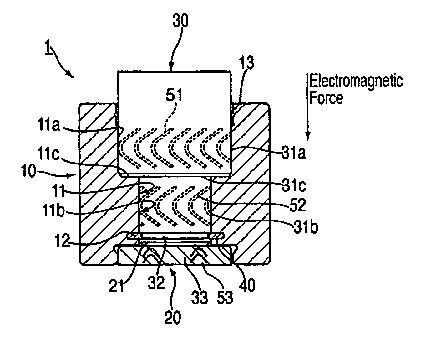
[0033]The first embodiment (Embodiment 1) of the invention in this application is described below.

[0034]FIG. 1 shows a vertical cross-sectional view of a fluid bearing system 1 of the first embodiment. The fluid bearing system 1 of the first embodiment is equipped with a cylindrical bearing case 10 having a cylindrical hole 11 (11a, 11b) in its center, an end plate 20 that seals one end of the lower part of the bearing case 10 and a shaft 30 that has at least one part inserted into and supported by the bearing housing formed by bearing case 10 and end plate 20. The cylindrical hole 11 consists of a large part 11a and a small part 11b. The shaft 30 is connected to the rotating load unit not shown in the figure. The shaft 30 may be manufactured as an integral part of the rotating load unit. Additionally, in some cases, a fixed unit may be attached to the shaft 30 in place of the rotating unit. In this case, the bearing case 10 is the rotating side. Furthermore, in this specification, ...

embodiment 2

[0046]FIG. 2 shows a vertical cross-sectional view of a fluid bearing system 1 of a second embodiment (Embodiment 2) of the invention of this application and the parts corresponding to Embodiment 1 have been assigned the same codes.

[0047]As shown in FIG. 2, when the dynamic fluid bearing mechanism 1 (alternatively, the fluid bearing system 1) of Embodiment 2 is compared to Embodiment 1, the only difference is in the position where the third dynamic pressure generating groove 53 is formed. In other words, while in Embodiment 1 the third dynamic pressure generating groove 53 was formed on the inner surface 21 of the end plate 20, in Embodiment 2, the third dynamic pressure generating groove 53 is formed on the step part 11c of stepped cylindrical hole 11 of bearing case 10. In addition, the small gap faced by said third dynamic pressure generating groove 53 and formed between the step part 11c of stepped cylindrical hole 11 and the surface of the step part 31c of stepped shaft 30, is ...

embodiment 3

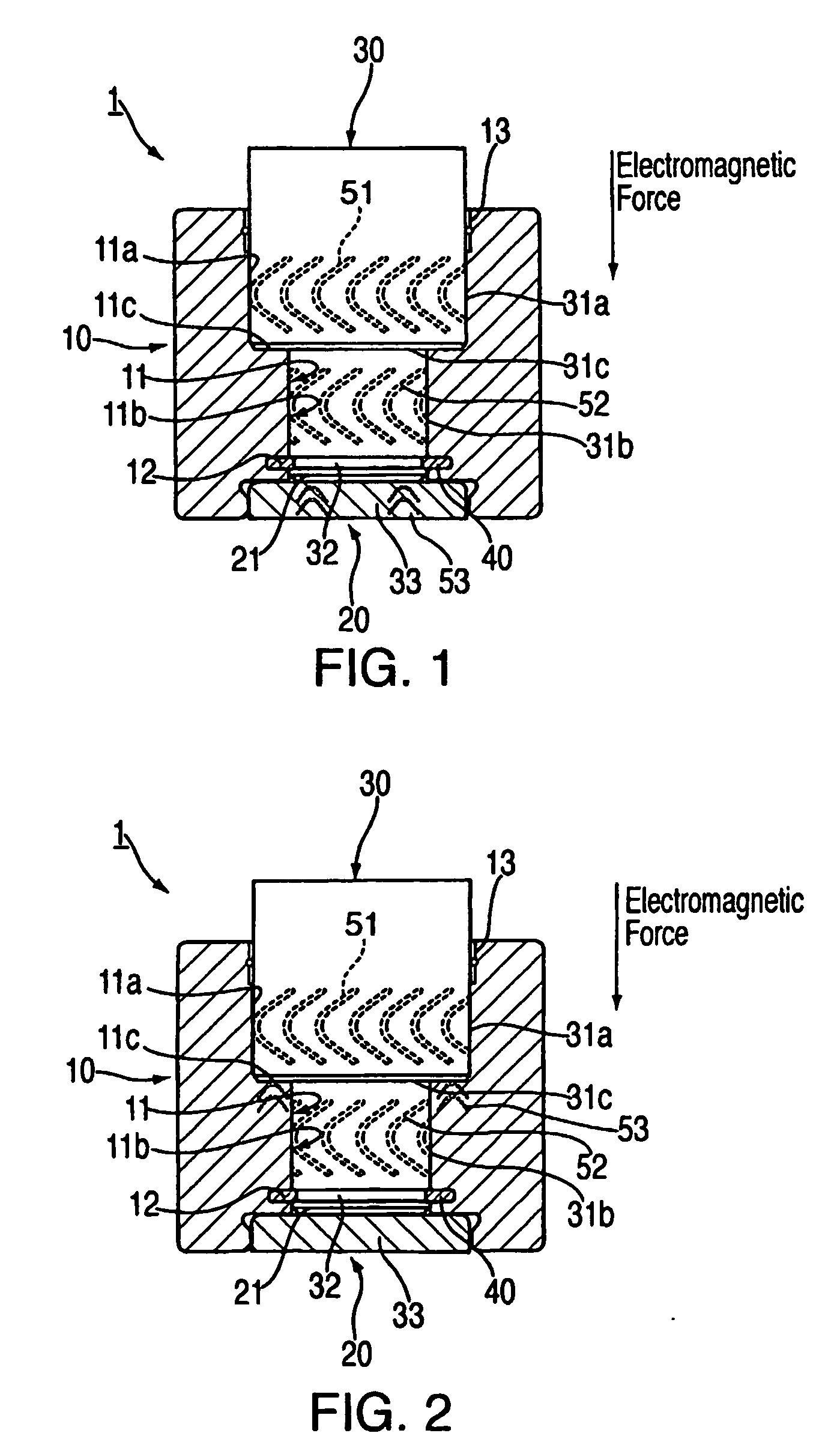
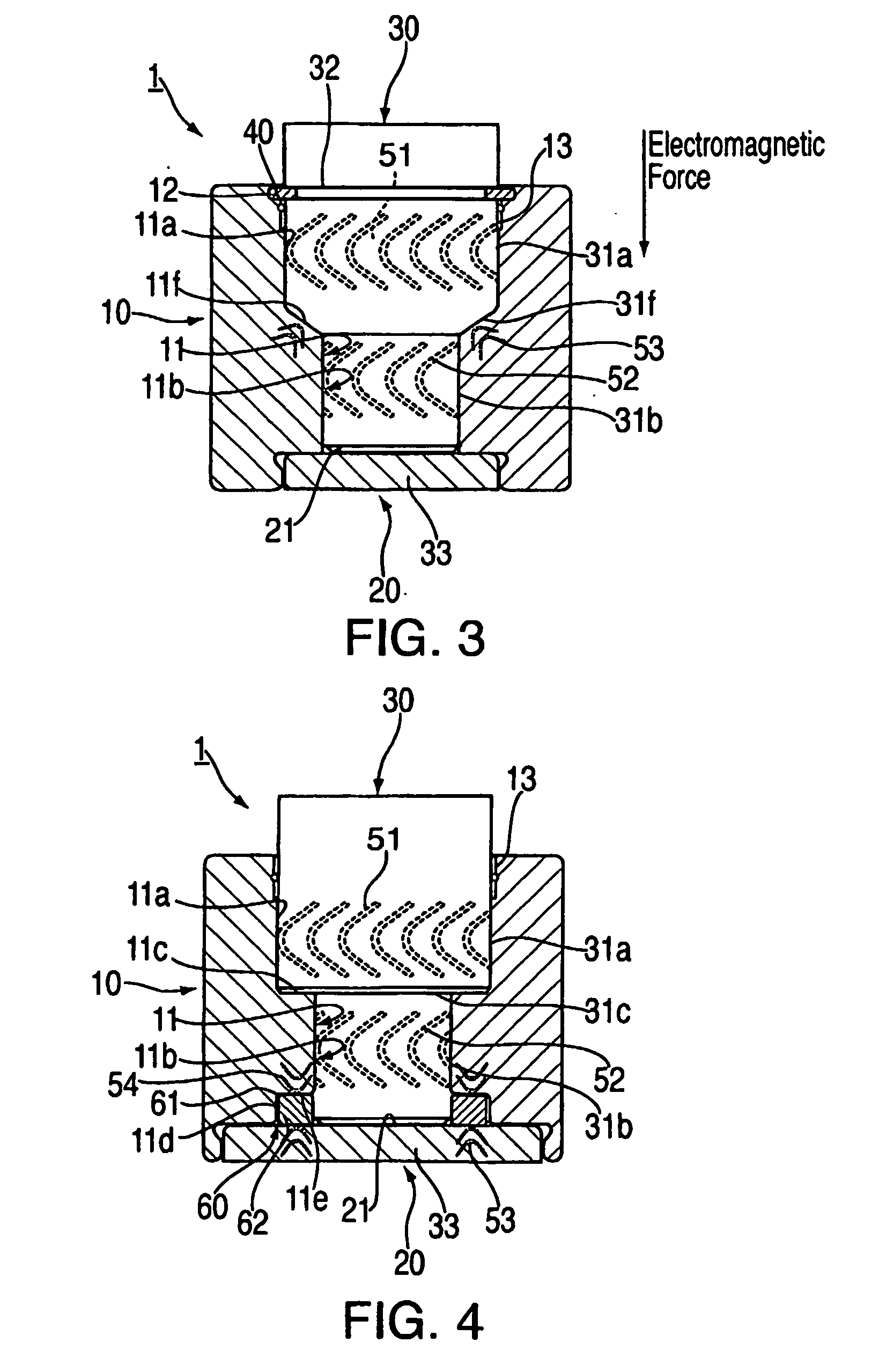
[0053]FIG. 3 is a diagram showing a vertical cross-sectional view of the present invention's third embodiment (Embodiment 3) of a fluid dynamic bearing mechanism 1, with the same labels for the parts that correspond with Embodiment 2.

[0054]The fluid dynamic bearing mechanism 1 of Embodiment 3 has a gradient in the bearing case 10's step part 11c of stepped-cylindrical hole 11. A step part 31c of stepped-shaft 30 has a tapered structure (designated by label 31f), such that the smaller side is in the direction of endplate 20. The third dynamic pressure groove 53 is formed at a tapered part 11f of the stepped cylindrical hole 11. The annular ring 40 is moved on the large-diameter part side of bearing case 10. Alternatively, the third dynamic pressure groove 53 can be formed on the external surface of the tapered part 31f of stepped-shaft 30.

[0055]In Embodiment 3, the small gap (which faces the third dynamic pressure groove 53) that is formed between the tapered part 11f and the externa...


PUM

PropertyMeasurementUnit
diameteraaaaaaaaaa
dynamic pressureaaaaaaaaaa
forcesaaaaaaaaaa

Abstract

A fluid dynamic bearing mechanism that can ensure bearing rigidity, reduce shaft loss torque, reduce power consumption, stabilize axial rotation, and improve rotational accuracy is disclosed. The fluid dynamic bearing mechanism being suitable for use in a hard disk drive. In the fluid dynamic bearing mechanism (equipped with a bearing case, endplate, and shaft) a cylindrical hole of the bearing case is changed to a stepped cylindrical hole that has a large diameter part and a small diameter part. The shaft is changed to a stepped shaft that has a large diameter part and a small diameter part. On the outer circumference of either the large diameter part of the stepped cylindrical hole, or the large diameter part of the stepped shaft, a first dynamic pressure groove is be formed. On the outer circumference of either the small diameter part of the stopped cylindrical hole or the small diameter part of the stepped shaft, a second dynamic pressure groove is being formed. On the surface of step part of the stepped cylindrical hole, the third dynamic pressure groove is formed. The small gaps that face each of the three dynamic pressure grooves are filled with a dynamic pressure generating lubricating oil.

Description

BACKGROUND OF THE INVENTION[0001]1. Field of the Invention[0002]The present invention relates to fluid dynamic bearing demonstrating bearing functionality especially for forces in both the radial and axial directions. More particularly, the invention relates to a fluid dynamic bearing that reduces shaft torque loss while maintaining bearing rigidity.[0003]2. Description of Related Art[0004]The trend in recent years is towards greater-capacity, smaller-sized office automation equipment such as computers, etc., which use spindle motors in drive mechanisms for peripheral devices such as hard disk drives, etc. Therefore, spindle motors that demonstrate reliability in terms of motor positioning accuracy (NRRO (asynchronous vibration)), noise, acoustic lifespan, and rigidity, etc, are in great demand.[0005]In previous years, bearing devices formed by combining multiple ball bearings were commonly used in spindle motors. However, recently, the demand for increased recording capacity, impro...

Claims


Application Information

Patent Timeline
Patent Type & Authority Applications(United States)
IPC IPC(8): F16C32/06H02K7/08G11B5/82F16CF16C33/10
CPCF16C17/105F16C17/107F16C2370/12
Inventor OBARA, RIKURO
Owner MINEBEA CO LTD
Why Eureka
Try Eureka