Elevated coupling liquid temperature during HIFU treatment method and hardware

a technology of coupling liquid temperature and hifu, which is applied in the field of high-intensity focused ultrasound for medical treatment procedures and equipment, can solve the problems of high collateral tissue damage, unviable tissue and will die, and the lesion cannot extend all the way back to the surfa

a technology of coupling liquid temperature and hifu, which is applied in the field of high-intensity focused ultrasound for medical treatment procedures and equipment, can solve the problems of high collateral tissue damage, unviable tissue and will die, and the lesion cannot extend all the way back to the surfa

US20080281200A1Inactive Publication Date: 2008-11-13US HIFU

Image

  • Elevated coupling liquid temperature during HIFU treatment method and hardware
  • Elevated coupling liquid temperature during HIFU treatment method and hardware
  • Elevated coupling liquid temperature during HIFU treatment method and hardware

Examples


Embodiment Construction

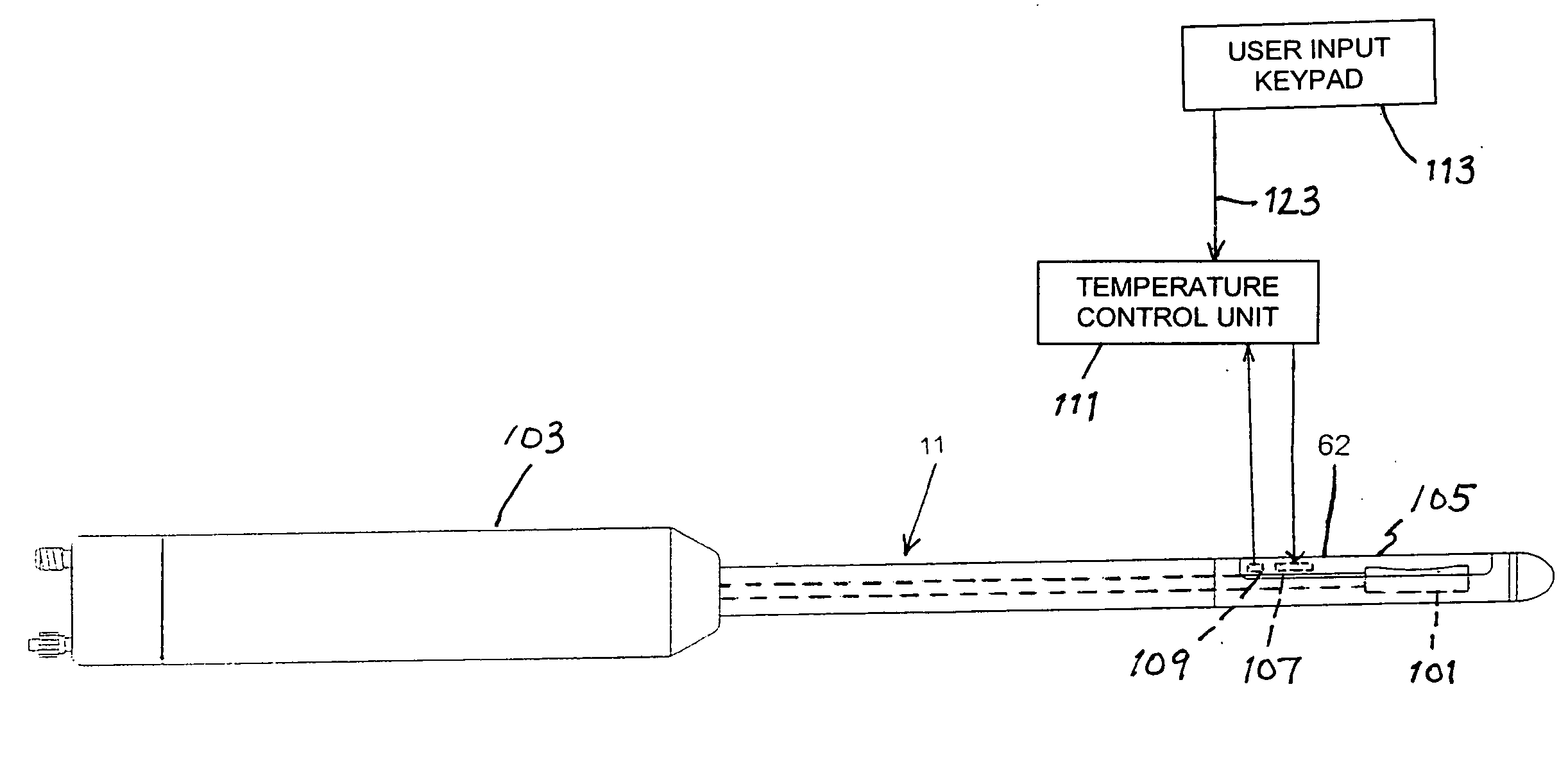
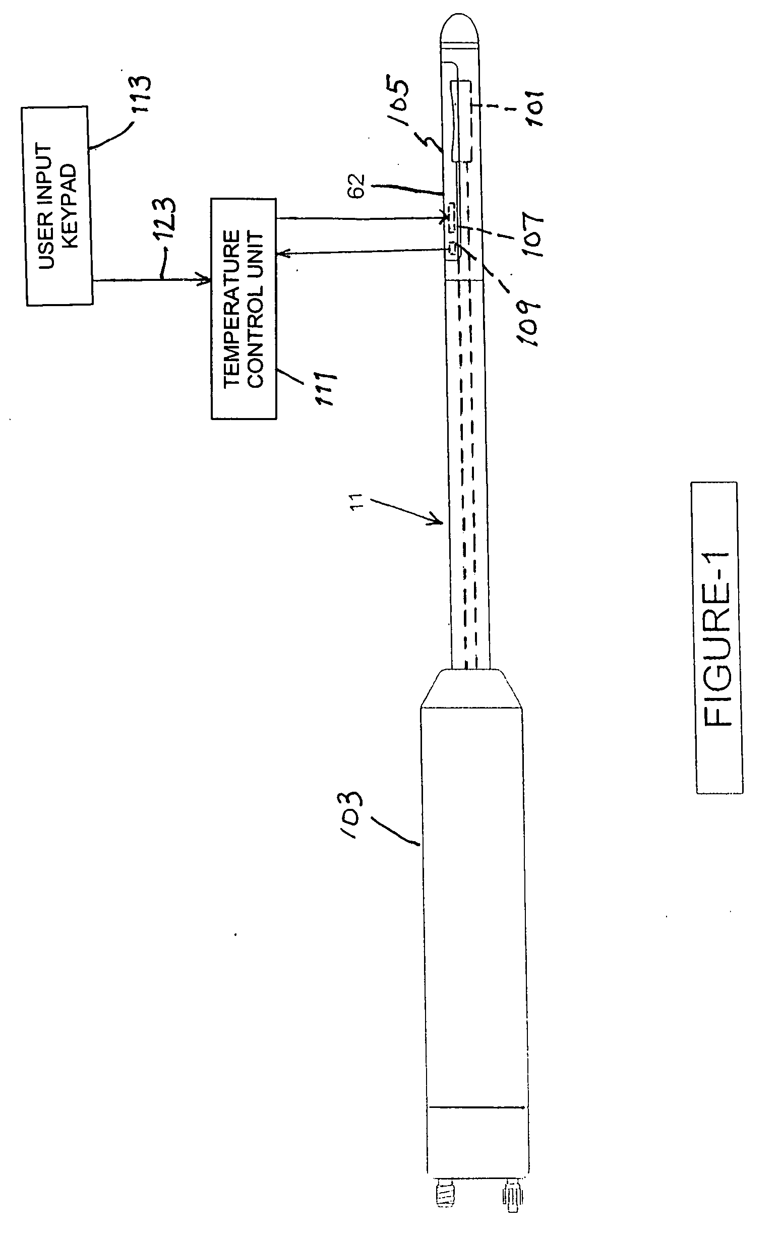
[0043]FIG. 1 depicts a high-intensity focused ultrasound probe 11 including a handle or handgrip 103 and a transducer head 101 disposed inside an expandable liquid chamber or bolus 62. The transducer head is a source of ultrasonic vibrations in operative engagement with bolus 62. Probe 11 further includes means for controlling a temperature of liquid in the bolus 62 while an applicator surface 105 (a surface of a flexible wall of the bolus, not separately designated) is in contact with an organ surface of a patient to control temperature elevation in tissues of the organ between a focal region and the organ surface to necrose the tissues to within a desired distance from the organ surface. Modes of operating probe 11 with bolus temperature control are discussed below, after a description of a liquid processing and transport system for the probe.

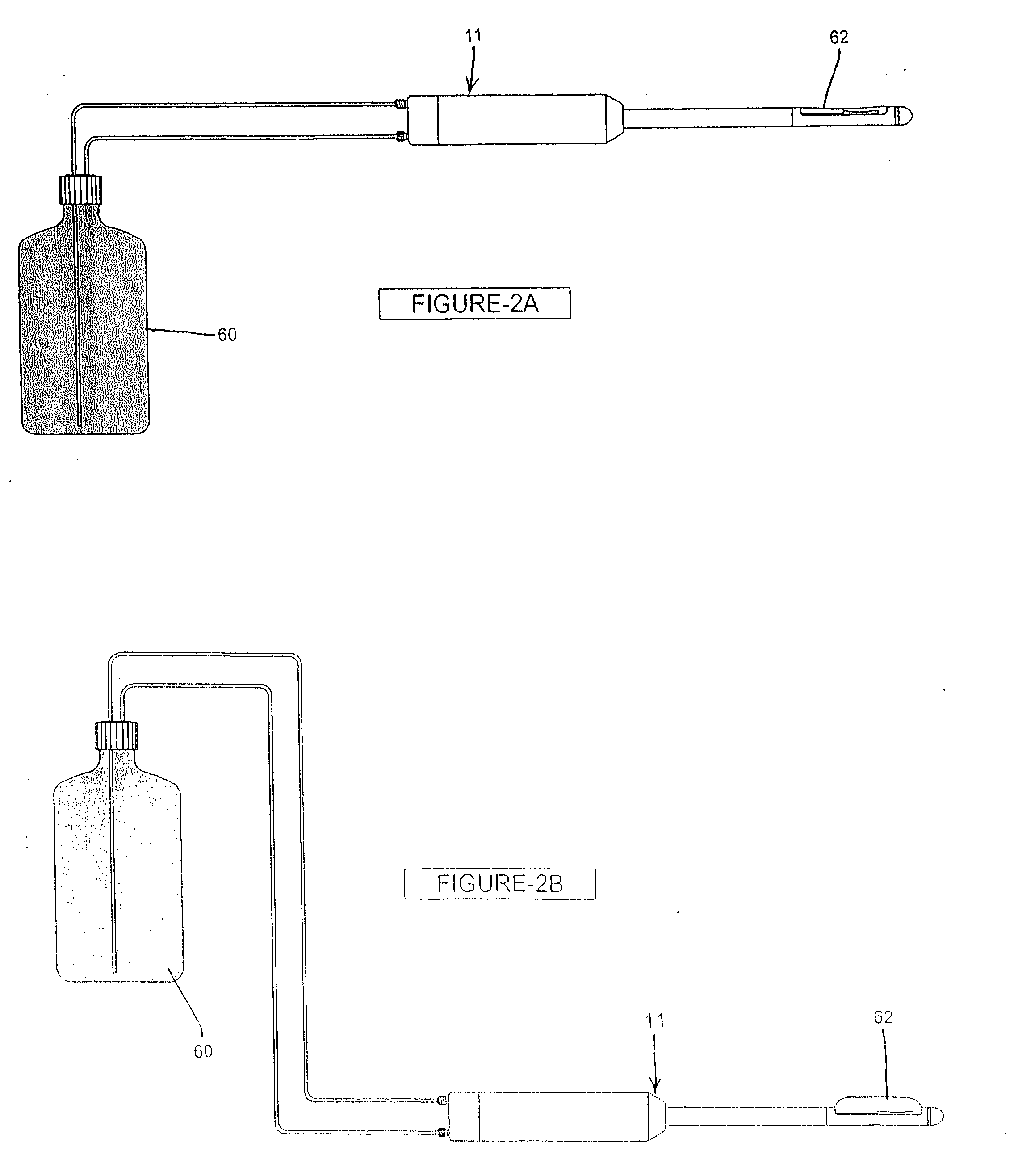
[0044]A liquid processing and transport mechanism for a medical instrument such as a high intensity focused ultrasound probe 11 is shown in ...


PUM


Abstract

A medical procedure utilizes a high-intensity focused ultrasound instrument having an applicator surface, a liquid-containing bolus or expandable chamber acting as a heat sink, and a source of ultrasonic vibrations, the applicator surface being a surface of a flexible wall of the bolus, the source of ultrasonic vibrations being in operative contact with the bolus. The applicator surface is placed in contact with an organ surface of a patient, the source is energized to produce ultrasonic vibrations focused at a predetermined focal region inside the organ, and a temperature of liquid in the bolus is controlled while the applicator surface is in contact with the organ surface to control temperature elevation in tissues of the organ between the focal region and the organ surface to necrose the tissues to within a desired distance from the organ surface.

Description

BACKGROUND OF THE INVENTION[0001]This invention relates to medical treatment procedures and apparatus using high-intensity focused ultrasound. More particularly, this invention relates to such procedures and apparatus for inducing controlled tissue necrosis.[0002]High Intensity Focused Ultrasound (“HIFU”) devices for use in various surgical procedures have been described in medical literature since the late 1940's. These devices use the same type of energy source as is found in SONAR transmitters or more recently, Diagnostic Ultrasound Scanners. However, instead of transmitting these waves through the body as a collimated beam, HIFU transmitters instead focus the acoustic energy to a theoretical point distal from the transducer / tissue interface much the same as a magnifying glass focuses light beams. The point at which the acoustic energy intensity is greatest is called the focal point. If the energy intensity is great enough at this point, the tissue will begin to heat. As the ener...

Claims


Application Information

Patent Timeline
13 Nov 2008
Publication
US20080281200A1
IPC
A61B17/00
CPC
A61B2017/00084; A61B2017/2253; A61B2018/00023; A61N7/022
Inventors
VOIC, DAN; MANNA, RONALD R.