Eureka AIR delivers breakthrough ideas for toughest innovation challenges, trusted by R&D personnel around the world.

Radar level gauge system having limited transmission power

Active Publication Date: 2008-11-20
ROSEMOUNT TANK RADAR
View PDF6 Cites 11 Cited by
  • Summary
  • Abstract
  • Description
  • Claims
  • Application Information

AI Technical Summary

Benefits of technology

[0011]In view of the above-mentioned and other drawbacks of the prior art, a general object of the present invention is to provide an improved radar level gauge system, and in particular a radar level gauge system capable of combining a sufficiently low transmission power to comply with various regulations with a high quality of measurement, including measurement accuracy.
[0019]The present invention is based upon the realization that the desired low transmission power level, in combination with high accuracy measurement can be obtained by simultaneously adjusting the power levels of the transmitted electromagnetic signals and of the returned reflected electromagnetic signals with different gain factors, where the gain factor for the transmitted electromagnetic signals is lower than for the returned reflected electromagnetic signals, and by doing this between the transceiver input / output terminal and the antenna. For example, the transmitted electromagnetic signals may be attenuated and the returned reflected electromagnetic signals may be amplified, or both the transmitted and the returned reflected electromagnetic signals may be attenuated, but the transmitted signals attenuated more than the returned reflected signals. In this manner a reduction in the transmission power and a maintained isolation (sufficiently low local oscillator leakage) of the receiver branch can obtained simultaneously, through the inclusion of relatively uncomplicated and affordable circuitry between the transceiver input / output terminal and the antenna.
[0023]This may be achieved by designing the power level adjusting circuitry so that it has a small physical extension in relation to a wavelength of the transmitted / received electromagnetic signals. For example, the power level adjusting circuitry may advantageously be designed in such a way that an equivalent length of a transmission path of the electromagnetic signals therethrough is considerably shorter than the wavelength of the electromagnetic signals, such as shorter than half the wavelength of the electromagnetic signals. Consequently, the extension of the power level adjusting circuitry can be permitted to be larger for a larger wavelength of the electromagnetic signals. This minimum physical extension can, for example, be realized by not implementing various stub lines etc that are typically used for microwave circuits, and thereby trading optimum performance for a reduced variability of the equivalent waveguide length. physical extension of said power level amplifying circuitry is minimized in relation to a wavelength of said electromagnetic signals, in such a way that an equivalent length of a transmission path of said electromagnetic signals through said power level amplifying circuitry is reduced to a distance smaller than said wavelength of the electromagnetic signals.
[0024]The “equivalent waveguide length” or equivalent length of transmission path, which is sometimes also referred to as “inner length”, is a property that indicates how circuitry influences electromagnetic signals passing therethrough with respect to transmission parameters, such as reflection due to discontinuities in impedance along the route of the electromagnetic signals through the circuitry. The effect of the various reflections can be expressed as an equivalent length of a transmission path, or, in other words, an equivalent waveguide length, which is equivalent to a group delay of the electromagnetic signals. It should be noted that this does not necessarily mean that the circuitry in question is a waveguide or even includes a waveguide, but that it can be represented by a waveguide having a certain length when describing its impact on signals passing therethrough. By keeping the equivalent waveguide length substantially constant and / or monitoring the changes in the equivalent waveguide length and compensating for these changes, an improved measurement accuracy can be achieved, since the distance between the surface to be gauged and a reference position typically depends on the equivalent waveguide length of the circuitry between the antenna and the terminal of the transceiver where a signal indicative of the distance is output.

Problems solved by technology

Such a limited transmission power in combination with high quality measurement is readily achievable in a radar level gauge system having a transceiver with separated transmitter output and receiver input, the output being connected to a transmission antenna, and the input to a receiver antenna, but considerably more difficult to achieve for a transceiver having a common transceiver input / output terminal.
In present solutions for achieving an low transmission power level in a radar level gauge having such a transceiver with a common input / output terminal, and a single antenna, it has proven to be very difficult, if at all possible, to at the same time achieve a sufficiently low output power, say −40 dBm (100 nW) or lower and a sufficiently accurate measurement of the filling level.
In this solution, however, the desired combination of low transmission power and high quality of measurement is difficult to obtain.

Method used


Image

  • Radar level gauge system having limited transmission power
  • Radar level gauge system having limited transmission power
  • Radar level gauge system having limited transmission power

Examples


Embodiment Construction

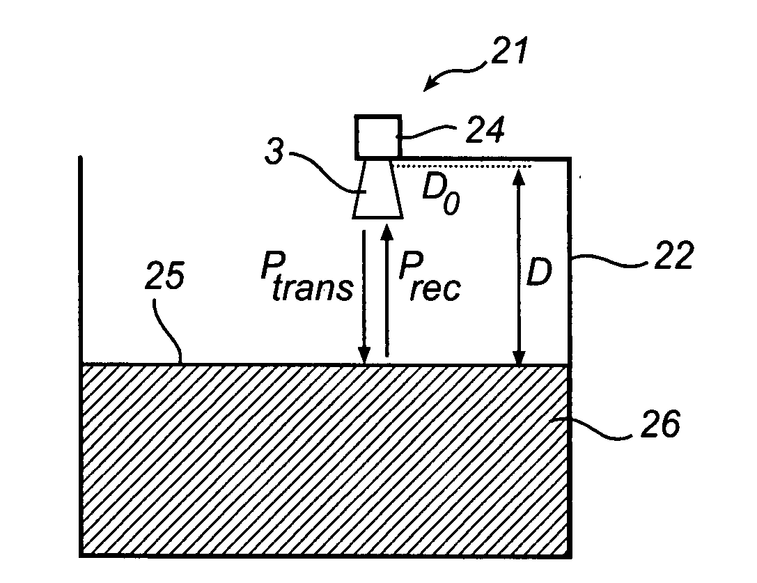
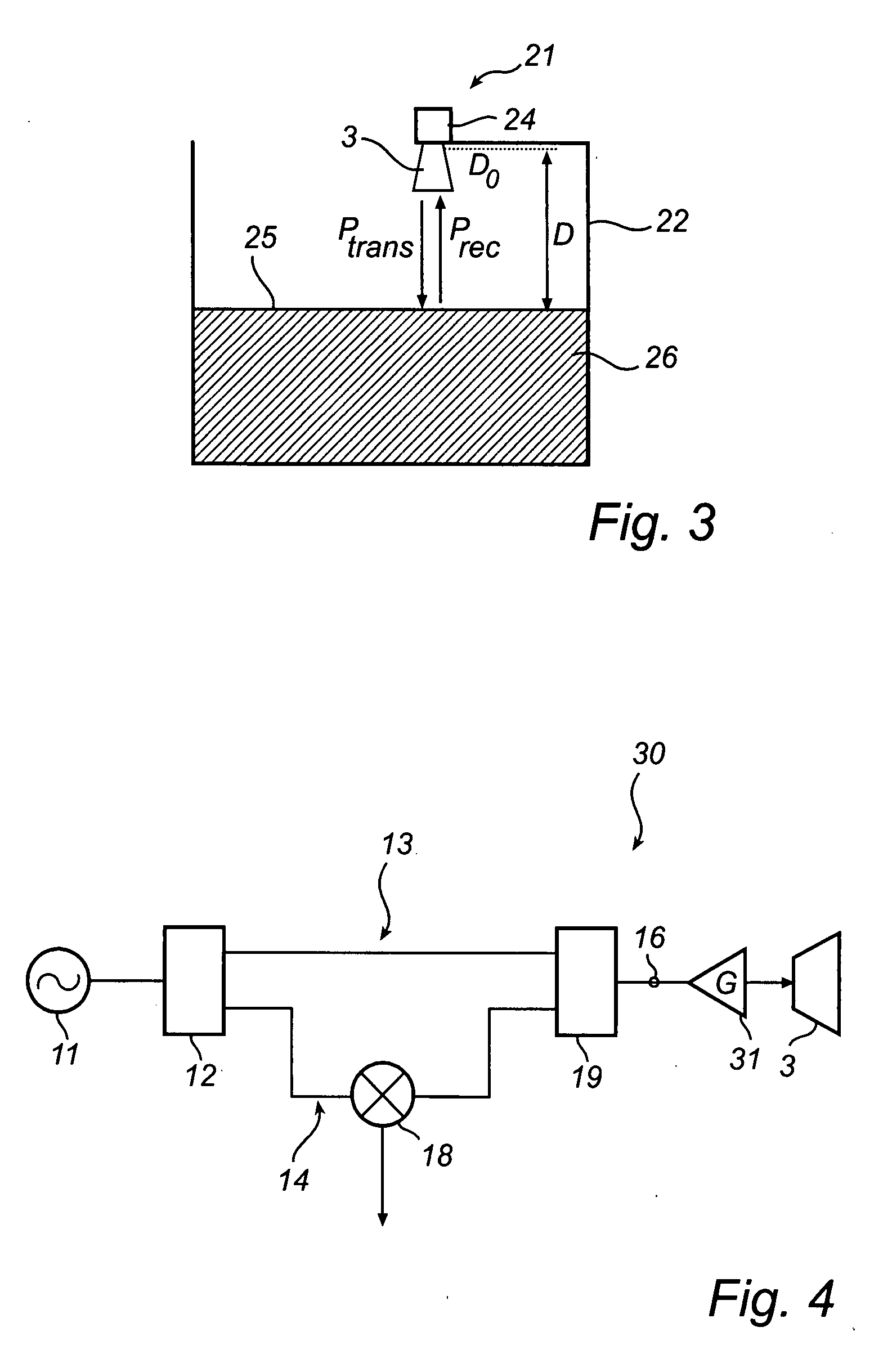
[0032]In the present description, embodiments of the present invention are mainly described with reference to a radar level gauge system having a horn antenna and being mounted on an open tank containing a product. It should be noted that this by no means limits the scope of the invention, which is equally applicable to radar level gauge systems implemented in other applications, open, semi-open as well as closed, such as for level determination in open tanks, floating roof tanks, reservoirs, rivers and other watercourses, etc.

[0033]Moreover, the radar level gauge system according to the present invention may be equipped with any other type of antenna or mode converter, such as a patch antenna, a rod antenna or an array antenna.

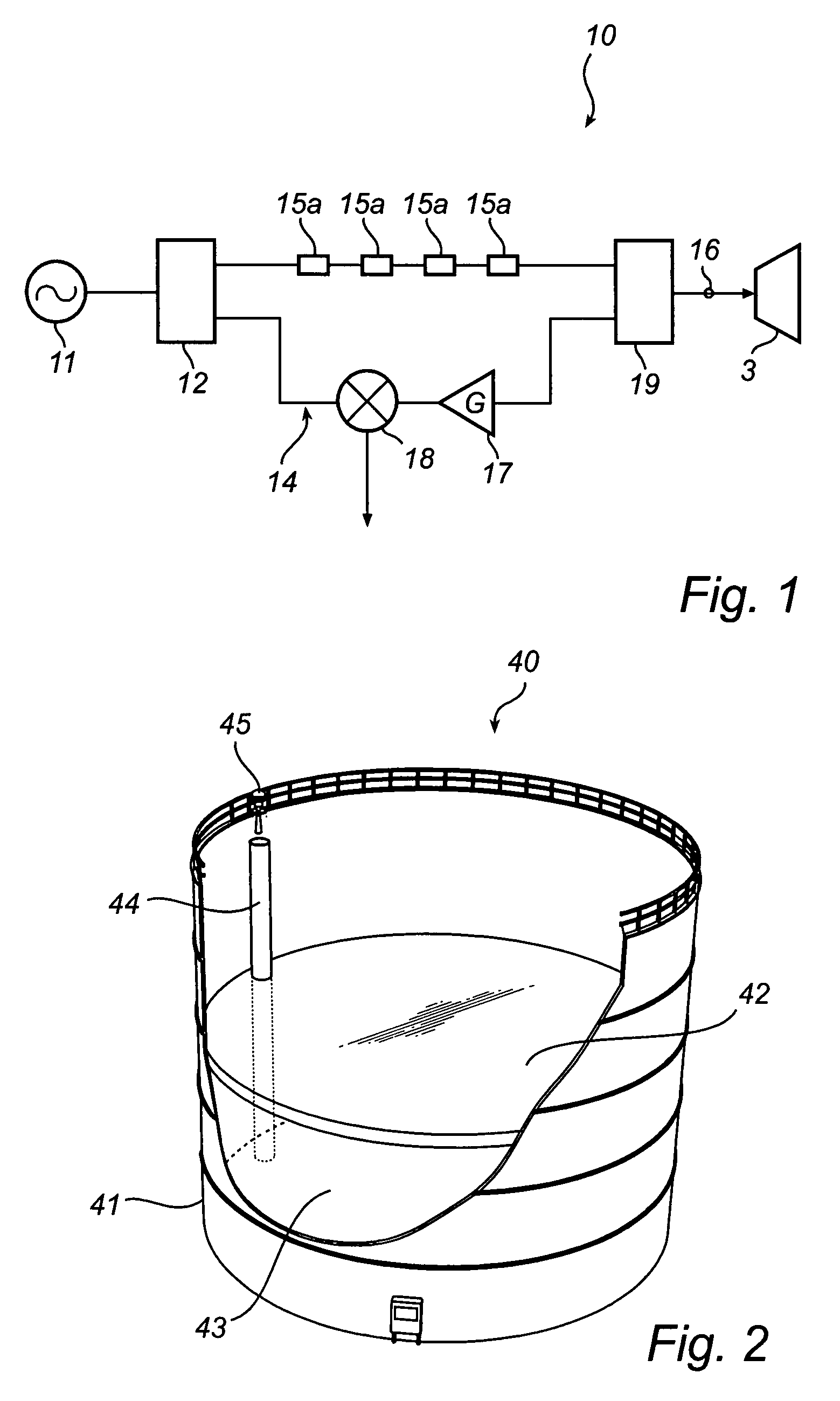
[0034]FIG. 2 illustrates an exemplary semi-open application for the radar level gauge system according to the present invention, in the form of a floating roof tank system.

[0035]In FIG. 2, a floating roof tank system 40 is shown, with a tank 41 having a roof ...


PUM


Abstract

A radar level gauge system, for determining a filling level of a product contained in a tank, the radar level gauge system comprising a transceiver including a signal generator for generating electromagnetic signals for transmission; a transmitter branch for transmitting the electromagnetic signals; and a receiver branch for receiving electromagnetic signals, the transmitter branch and the receiver branch each being connected to a transceiver input / output terminal. The radar level gauge system further comprises a propagation device for allowing transmitted electromagnetic signals to propagate towards a surface of the product inside the tank, where signals are reflected, and for returning reflected electromagnetic signals back from the surface of the product; processing circuitry connected to the transceiver and configured to determine the filling level based on the reflected electromagnetic signals; and power level adjusting circuitry connected between the transceiver input / output terminal and the propagation device, and configured to adjust a power level of the transmitted electromagnetic signals by a transmission gain factor, and to adjust a power level of the returned reflected electromagnetic signals by a reception gain factor, the transmission gain factor being smaller than the reception gain factor, wherein the power level adjusting circuitry comprises at least one active component.

Description

TECHNICAL FIELD OF THE INVENTION[0001]The present invention relates to a radar level gauge system, for level determination of a product, in particular a radar level gauge system having a limited transmission power.TECHNICAL BACKGROUND[0002]Radar level gauge systems are today in use in a variety of fields of application for accurate level determination, as well as for determination of other product parameters, such as temperature, flow etc. For determining the level of a product by means of a radar level gauge system, electromagnetic signals are transmitted and propagated, usually by means of an antenna, towards a surface of the product, where signals are reflected. The reflected signals are received by the radar level gauge system, and the distance between a reference position and the surface of the product is determined by comparing the transmitted signals with the reflected signals. Based on this distance, the filling level can be determined.[0003]Especially in open or semi-open a...

Claims


Application Information

Patent Timeline
IPC IPC(8): G01F23/00
CPCG01F23/284
Inventor JIRSKOG, ANDERS
Owner ROSEMOUNT TANK RADAR
Why Eureka
Eureka Blog
Learn More