Method and apparatus for inspection of materials

a three-dimensional space and material technology, applied in the direction of instruments, geological measurements, nuclear radiation detection, etc., can solve the problems of limiting the information given about the material content, unable to be precise, and devices can still be confused

Active Publication Date: 2008-11-20
KROMEK
View PDF6 Cites 59 Cited by
  • Summary
  • Abstract
  • Description
  • Claims
  • Application Information

AI Technical Summary

Benefits of technology

[0021]It is an object of the present invention to mitigate some or all of the above disadvantages of prior art scanning systems and methods.
[0022]It is a particular object of the present invention to provide a method and apparatus for x-ray scanning and preferably further for imaging of objects, and especially of containers of multiple objects or objects comprising multiple components, which provides additional information about their composition.

Problems solved by technology

These known apparatus and methods tend to give limited information about the material content.
There is therefore some limited merit in the use of dual energy detectors but it is far from being a precise explosive detector since many other items in luggage, such as soaps, creams, leather goods etc, are also dense organic materials.
Even with this resolution, such devices can still be confused by objects which are superimposed in the x-ray path, and will give no information concerning the crystalline or polycrystalline nature of an object.
Polycrystalline materials scatter x-rays and, the resulting x-ray image may hardly detect such polycrystalline material because a very large proportion of the X-rays which have not been absorbed by the material will have been scattered and so not received by the detector.
This is unfortunate as in security x-ray screening a number of threat items are polycrystalline in nature, in particular plastic explosives such as CP4, RDX, PETN and proprietary formulations thereof, drugs and the like and are therefore difficult to detect by using conventional x-ray systems.

Method used


Image

  • Method and apparatus for inspection of materials
  • Method and apparatus for inspection of materials
  • Method and apparatus for inspection of materials

Examples


Embodiment Construction

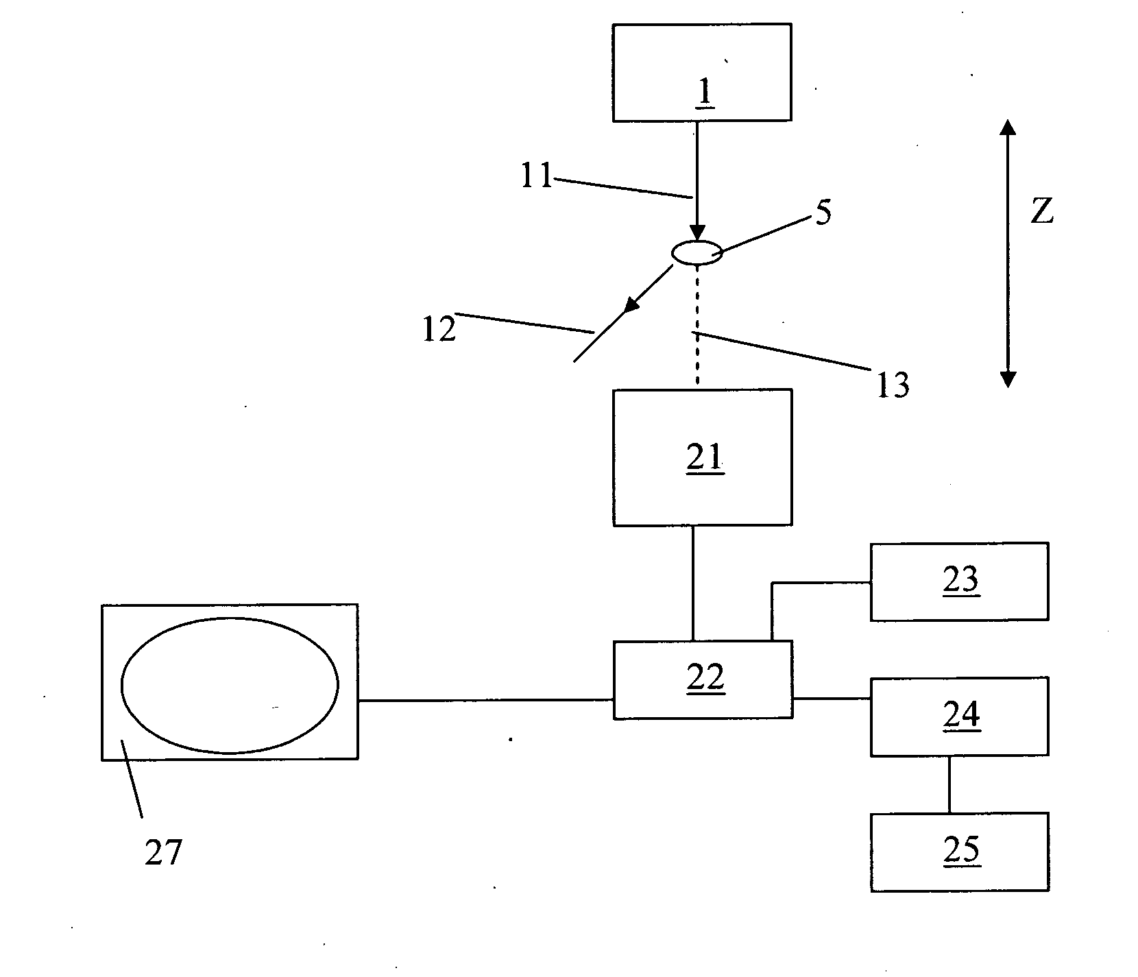
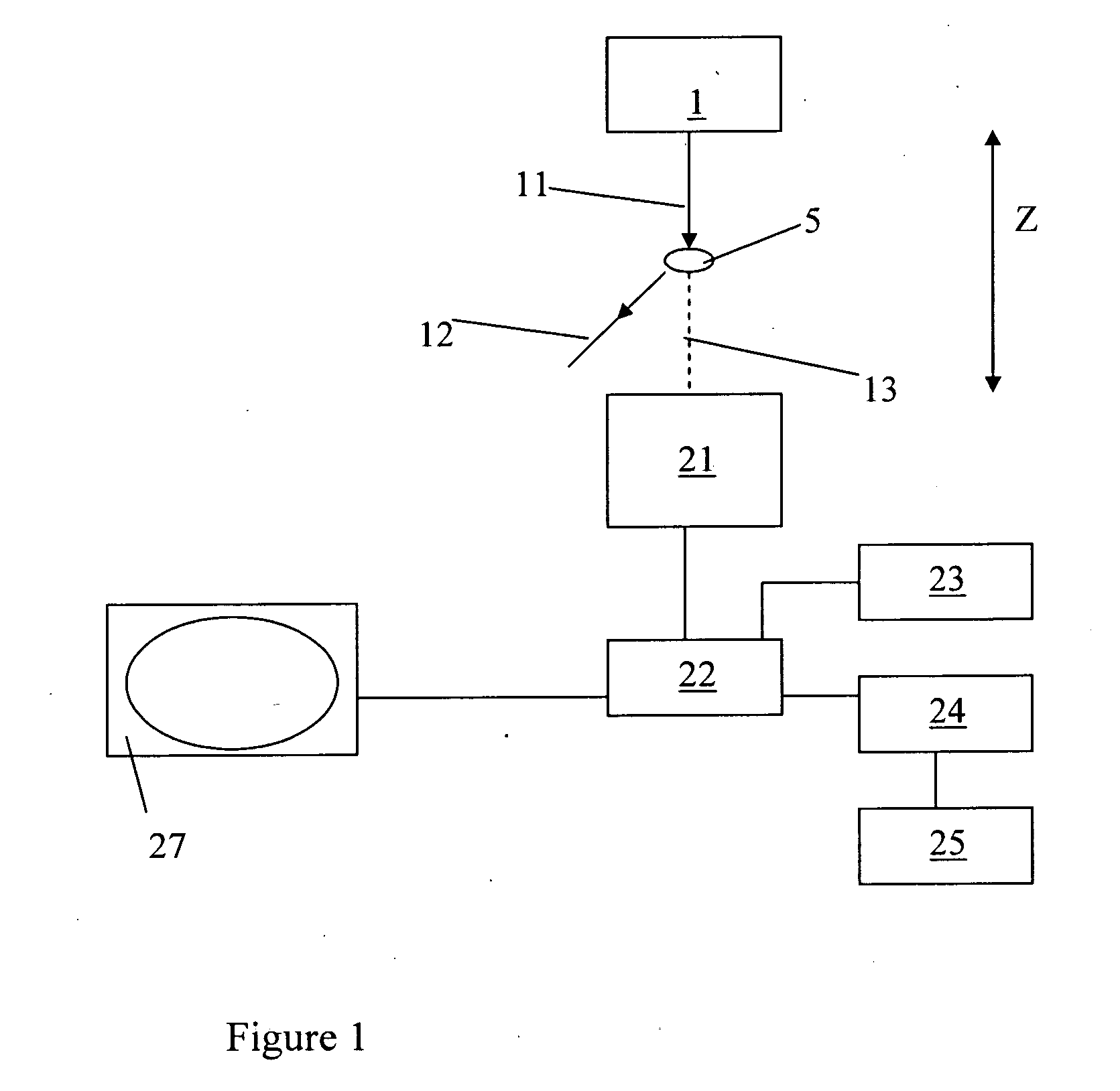
[0090]Referring first to the general schematic representation on FIG. 1, an x-ray source 1 and laterally spaced detector array 2 together define a scanning zone Z between them. In use, an object to be scanned is brought into and through the scanning zone in the usual manner, for example on a suitable conveyor belt (not shown).

[0091]In the illustrated example, a sample of crystalline material 5 sits in the scanning zone Z. An incident beam 11 from the x-ray source is illustrated. In the example, a diffracted beam 12 is diffracted at a characteristic angle in accordance with Bragg's law reducing the intensity of the transmitted beam 13 above and beyond the reduction which would be attributable to absorption alone. This illustrates the effect exploited by the invention.

[0092]The transmitted beam 13 is incident upon a detector array 21 which in a preferred embodiment comprises a plural linear array of cadmium telluride detector units.

[0093]The detector array 21 is in data communication ...


PUM


Abstract

A method and apparatus for obtaining radiation transmission data including providing a radiation source, e.g., x-ray or gamma-ray source, and a radiation detector system, e.g., x-ray or gamma-ray detection system, spaced therefrom to define a scanning zone therebetween, the detector system capable of detecting and collecting spectroscopically resolvable information about incident radiation. Collecting a dataset of information about radiation incident including transmissivity of an object in the scanning zone at at least one scanning position from radiation transmitted through the object and received at the detector system. Resolving each dataset spectroscopically across a plurality of frequency bands within the spectrum of the source; at least one of the frequency bands corresponding to a characteristically scattered wavelength of a target species to be identified. The absence of or substantial reduction in a transmitted signal intensity at the frequency band is interpreted as the presence of the said target species.

Description

FIELD OF THE INVENTION[0001]This invention relates to a method and apparatus for the inspection and characterisation of material in three-dimensional space, especially by imaging.BACKGROUND[0002]The invention in particular relates to an apparatus and method making use of high energy radiation such as x-rays or gamma-rays to scan objects where it is desirable to gain information about their internal contents and / or composition. This principle is widely employed for example in the security industry, but might also be employed in other areas, for example, without limitation, medical imaging, imaging for quality control purposes or the purposes of determining the integrity of the structure, or the like.[0003]X-Ray absorption has been used as the basis for screening objects to create some form of representational image of the contents or components thereof relative to each other in three-dimensional space. The thicker or more dense an object is then the more it will attenuate an x-ray be...

Claims


Application Information

Patent Timeline
Patent Type & Authority Applications(United States)
IPC IPC(8): G01T1/24
CPCG01N23/04G01V5/0016G01N23/2076
Inventor ROBINSON, MAXBASU, ARNAB
Owner KROMEK
Why Eureka
Try Eureka