Thin film magnetic head characterized in bias-applying layer

a thin film, magnetic head technology, applied in the field of thin film magnetic head, can solve the problems of asymmetry characteristic (output amplitude asymmetry) degraded, noise may be increased, etc., and achieve the effect of reducing noise and reducing output amplitude asymmetry

Active Publication Date: 2008-11-20
TDK CORPARATION
View PDF2 Cites 6 Cited by
  • Summary
  • Abstract
  • Description
  • Claims
  • Application Information

AI Technical Summary

Benefits of technology

[0005]However, in a thin film magnetic head of the prior art, for manufacturing reasons, the end faces at which the magnetoresistance effect element and the pair of bias-applying layers are opposed have always been formed at an inclination to the layering direction. Hence, in a thin film magnetic head of the prior art, magnetic flux in the bias magnetic field generated by the bias-applying layers has tended to flow into a free layer from the layering direction as well as from the direction of arrangement of the bias-applying layers (track width direction). In this case, of the free layer, magnetization occurs in the portion into which flux flows from the layering direction not only in the direction of arrangement of the bias-applying layers, but in the layering direction also, and so there are concerns that noise may be increased or that the asymmetry characteristic (output amplitude asymmetry) may be degraded.

Problems solved by technology

In this case, of the free layer, magnetization occurs in the portion into which flux flows from the layering direction not only in the direction of arrangement of the bias-applying layers, but in the layering direction also, and so there are concerns that noise may be increased or that the asymmetry characteristic (output amplitude asymmetry) may be degraded.

Method used


Image

  • Thin film magnetic head characterized in bias-applying layer
  • Thin film magnetic head characterized in bias-applying layer
  • Thin film magnetic head characterized in bias-applying layer

Examples


first embodiment

[0040](Configuration of Thin Film Magnetic Head)

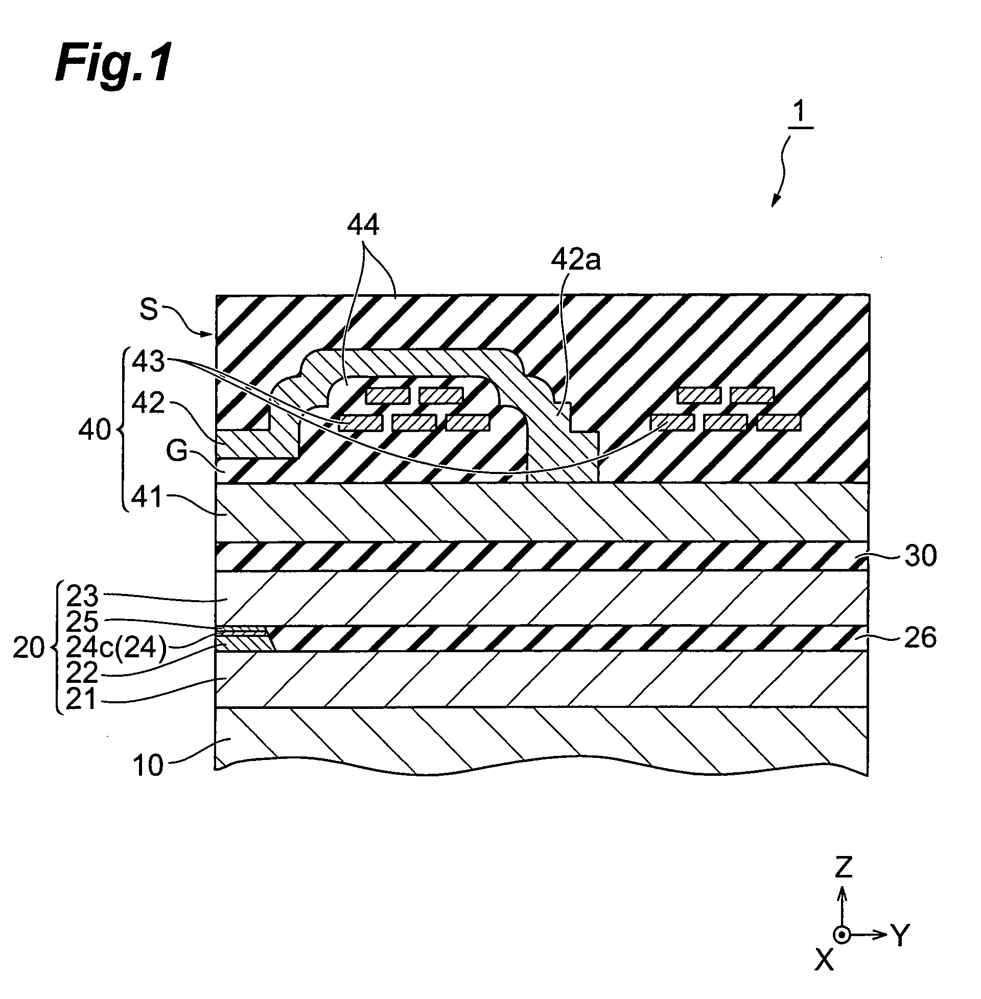
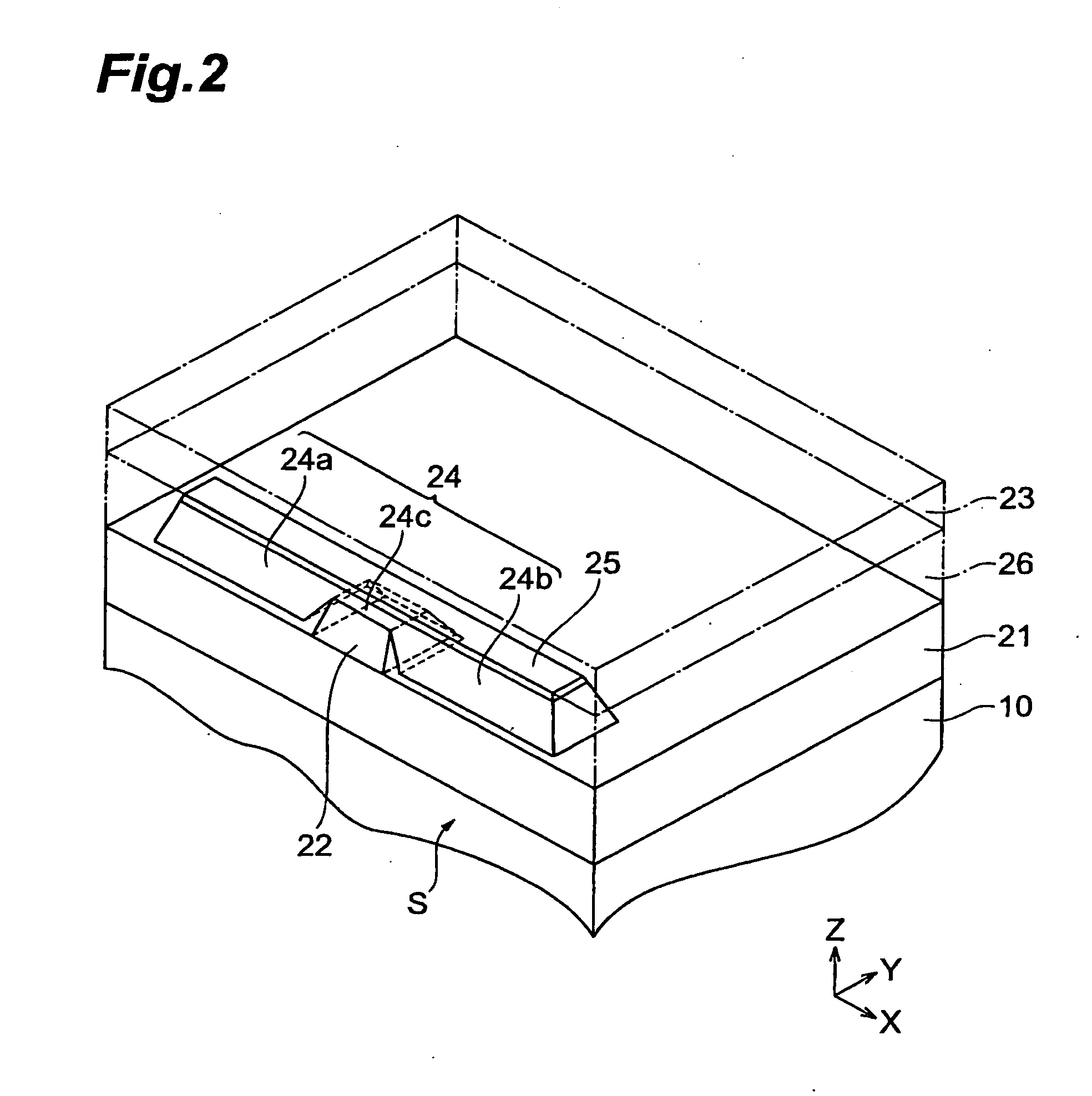
[0041]The configuration of the thin film magnetic head 1 of the first embodiment is explained, referring to FIG. 1 through FIG. 3.

[0042]The thin film magnetic head 1 is provided on the upper portion of a base 10, and is one portion of a magnetic head slider, not shown. The thin film magnetic head 1 is a hybrid-type thin film magnetic head, formed by layering on the base 10 in order a read head portion 20, having a TMR (Tunneling Magneto Resistance) element 22, described below; an insulating layer 30; and a recording head portion 40, as an induction-type electromagnetic transducer element for writing. In the thin film magnetic head 1, the end face on the left side in FIG. 1 is a media-opposed surface (air bearing surface) S, which opposes the recording surface of the hard disk, not shown. The base 10 is not shown in detail, a base layer of alumina (Al2O3) or another electrically insulating material is formed to a thickness of approximat...

example 1-1

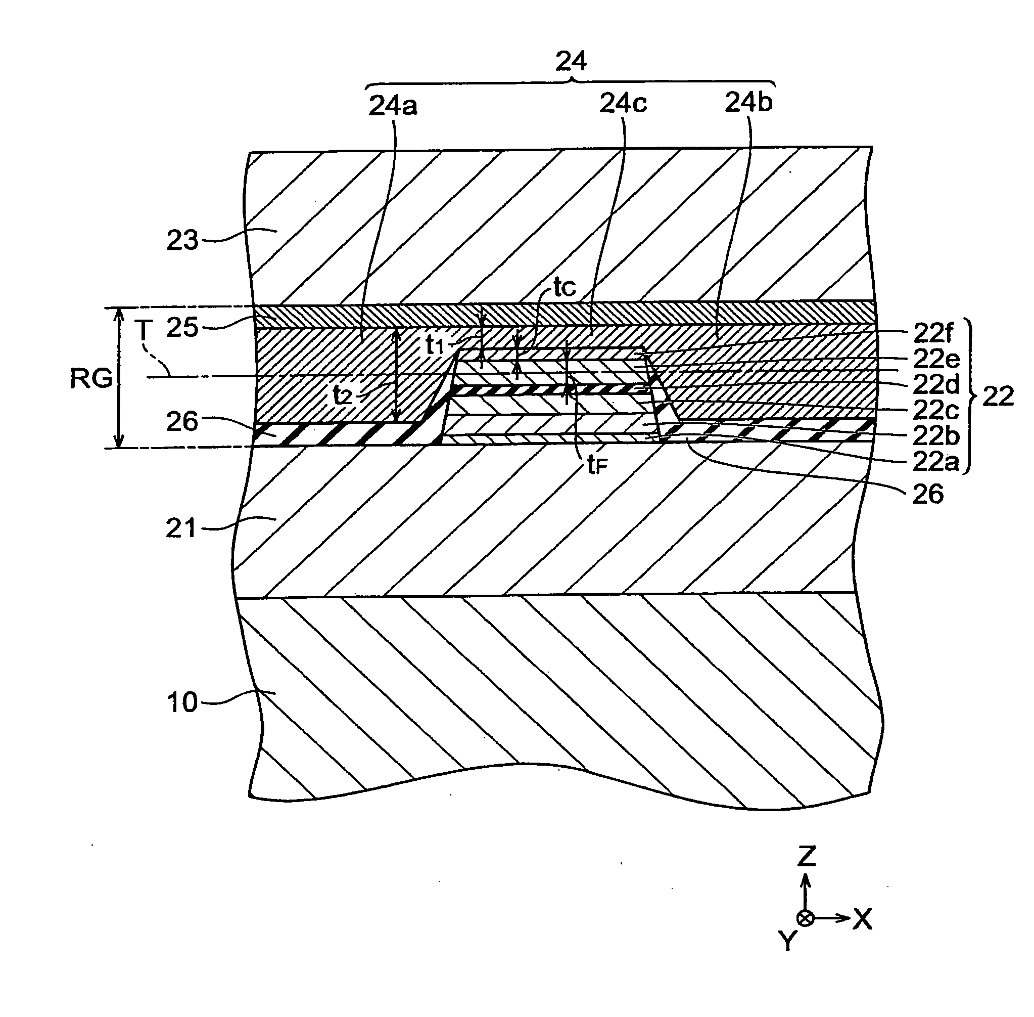
[0071]In example 1-1, the thickness t1 in the layering direction of the third portion 24c of the bias-applying layer 24 in the read head portion 20 of the thin film magnetic head 1 of the first embodiment is set to 10 nm, the thickness t2 in the layering direction of the first portion 24a and the second portion 24b of the bias-applying layer 24 is set to 30 nm, the read gap RG is set to 45 nm, the straight-line distance t4 between the bias-applying layer 24 and the lower magnetic shield layer 21 in the layering direction and the straight-line distance t5 between the bias-applying layer 24 and the upper magnetic shield layer 23 in the layering direction are both set to 7.5 nm, the distance t6 between the lower face of the first portion 24a and the lower face of the second portion 24b is set to 125 nm, the straight-line distance tC between the free layer 22e and the third portion 24c in the layering direction is set to 5 nm, the thickness tF of the free layer 22e in the layering direc...

example 1-2

[0072]In example 1-2, other than setting the thickness t1 in the layering direction of the third portion 24c of the bias-applying layer 24 to 12.5 nm and setting the straight-line distance tC in the layering direction between the free layer 22e and the third portion 24c to 2.5 nm, parameters were the same as in example 1-1.


PUM

PropertyMeasurementUnit
thicknessaaaaaaaaaa
thicknessaaaaaaaaaa
thickness tFaaaaaaaaaa

Abstract

A thin film magnetic head comprises a lower magnetic shield layer and an upper magnetic shield layer which are mutually opposed in the layering direction, a magnetoresistance effect element having a free layer, and a bias-applying layer which applies a bias magnetic field to the magnetoresistance effect element. The free layer is positioned between the lower magnetic shield layer and the upper magnetic shield layer, and is positioned on the side of the media-opposed surface. The bias-applying layer has a first portion, a second portion, and a third portion. The first portion and the second portion are positioned at a distance in the track width direction so as to enclose the magnetoresistance effect element therebetween. The third portion is positioned either between the magnetoresistance effect element and the lower magnetic shield layer or between the magnetoresistance effect element and the upper magnetic shield layer, and connects the first portion and the second portion.

Description

BACKGROUND OF THE INVENTION[0001]1. Field of the Invention[0002]This invention relates to a thin film magnetic head comprising a bias-applying layer.[0003]2. Related Background Art[0004]In the prior art, thin film magnetic heads have been known which comprise a magnetoresistance effect element and a pair of bias-applying layers which apply a bias magnetic field to the magnetoresistance effect element, and in which the pair of bias-applying layers are positioned with the magnetoresistance effect element therebetween and arranged in the track width direction (see for example Japanese Patent Laid-open No. 2002-123912).SUMMARY OF THE INVENTION[0005]However, in a thin film magnetic head of the prior art, for manufacturing reasons, the end faces at which the magnetoresistance effect element and the pair of bias-applying layers are opposed have always been formed at an inclination to the layering direction. Hence, in a thin film magnetic head of the prior art, magnetic flux in the bias mag...

Claims


Application Information

Patent Timeline
Patent Type & Authority Applications(United States)
IPC IPC(8): G11B5/10
CPCB82Y10/00B82Y25/00G01R33/093G11B5/3909G11B5/3932
Inventor OHTA, NAOKITANAKA, KOSUKESATO, KAZUKI
Owner TDK CORPARATION
Why Eureka
Try Eureka