
Tissue ablation apparatus and method

a tissue and apparatus technology, applied in the field of tissue ablation apparatus and method, can solve the problems that current ablative therapies have not considered nor provided solutions to these problems, and achieve the effects of reducing power levels, facilitating ablation, and facilitating ablation

Inactive Publication Date: 2008-11-20
ANGIODYNAMICS INC
View PDF6 Cites 1403 Cited by
  • Summary
  • Abstract
  • Description
  • Claims
  • Application Information

AI Technical Summary

Benefits of technology

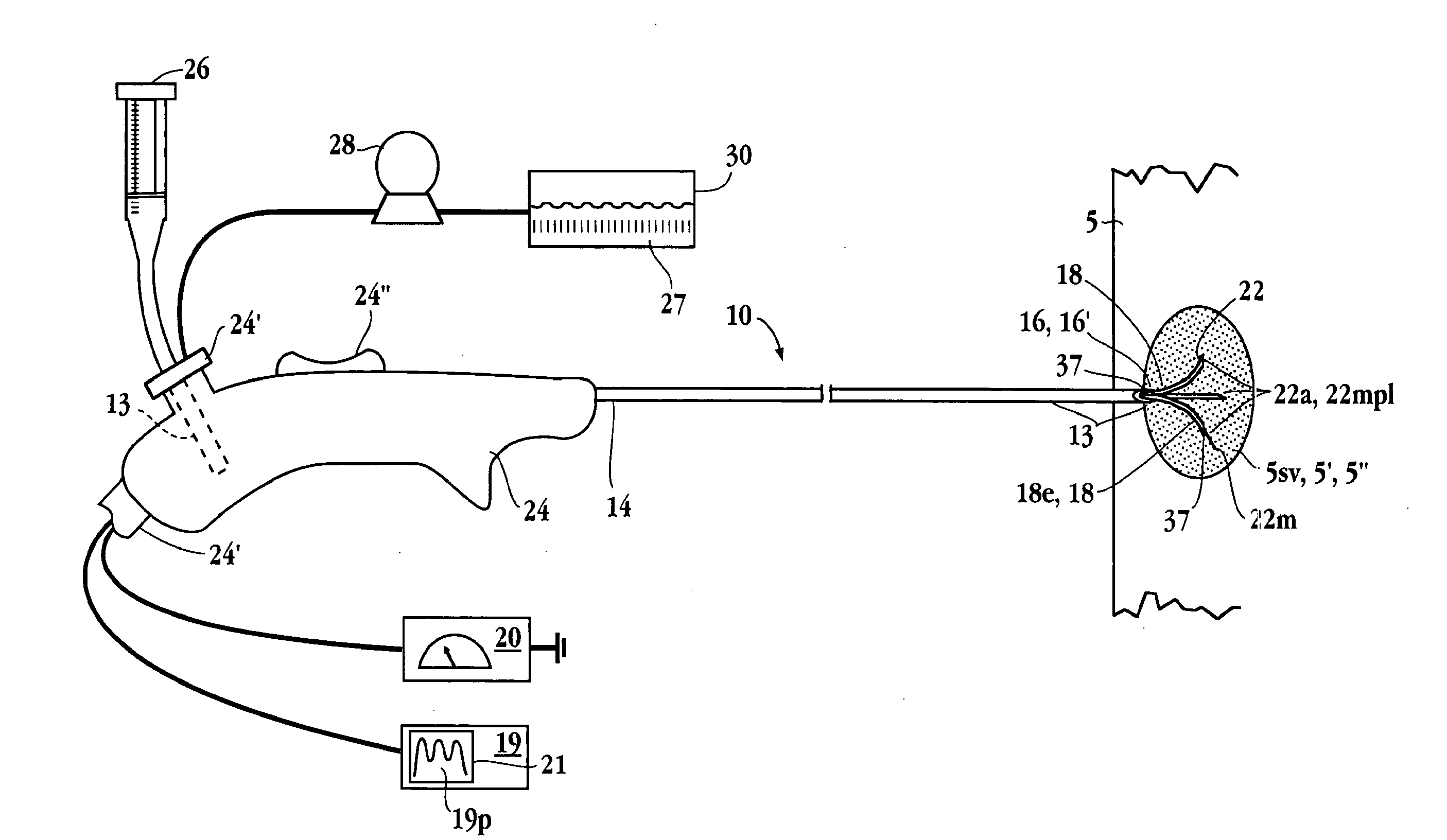
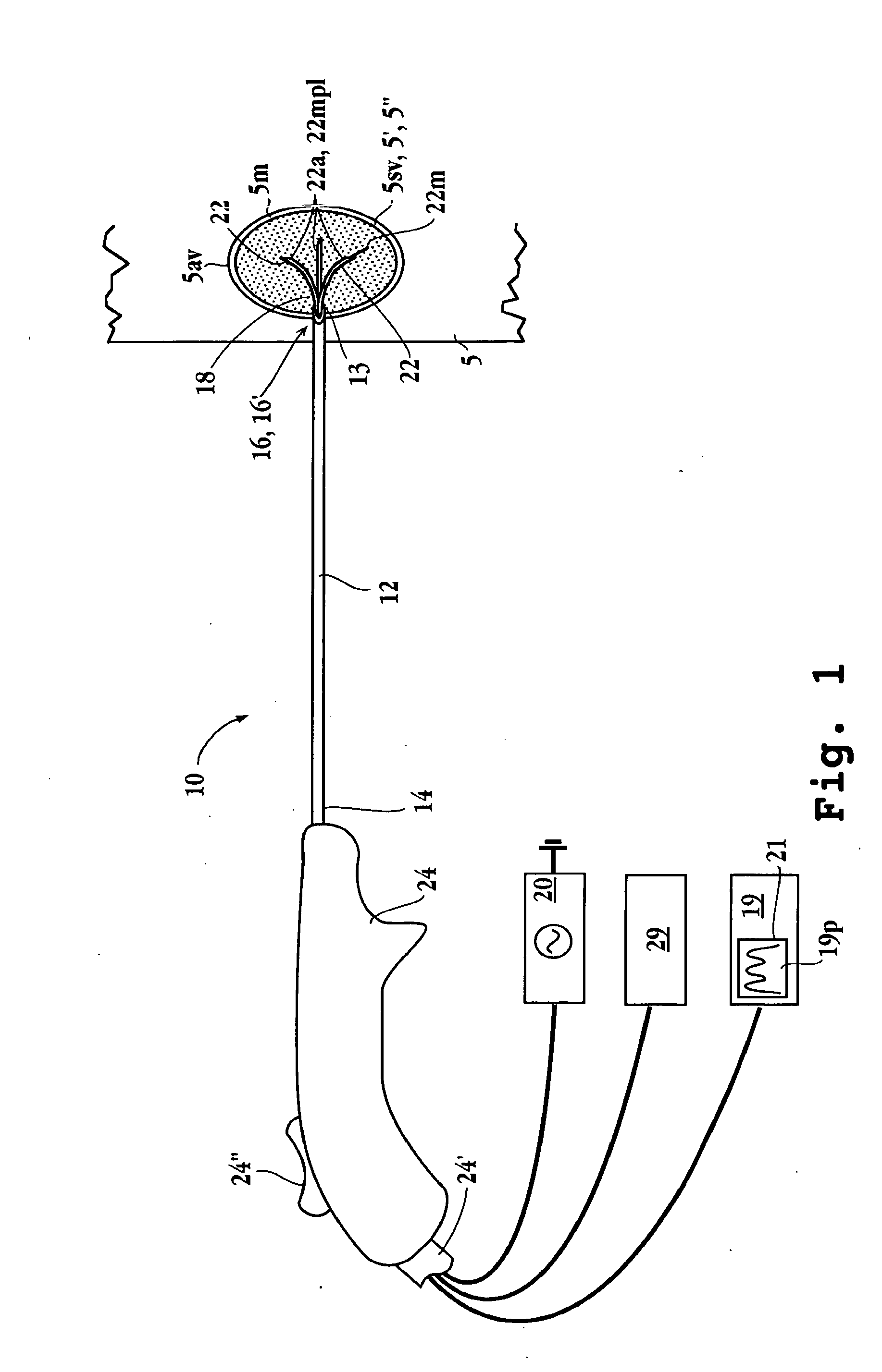
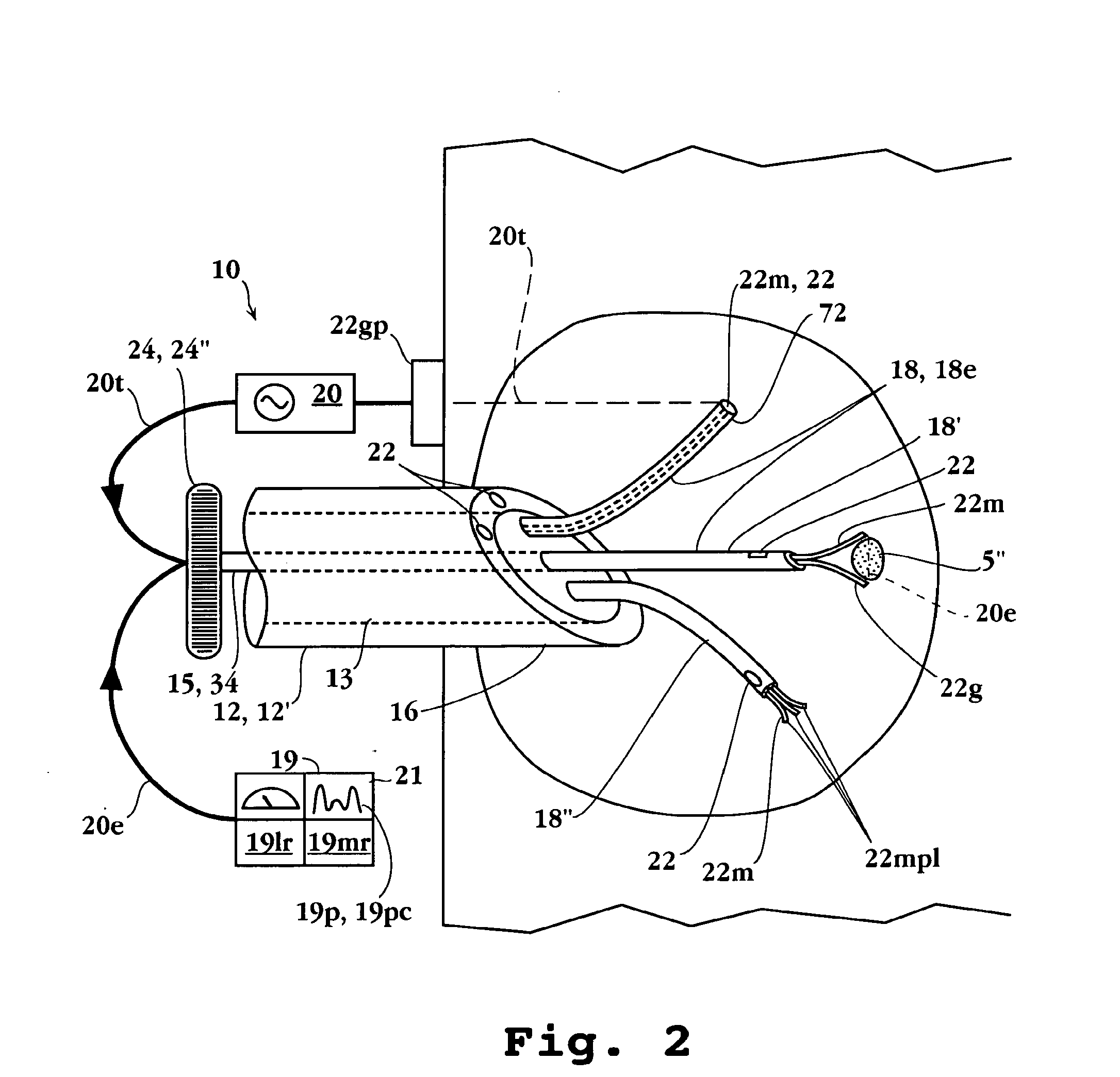
[0004]An embodiment of the invention provides an impedance controlled tissue ablation apparatus and method that utilizes impedance determinations, such as localized tissue impedance to optimize the delivery of radio-frequency or other electromagnetic energy to a target tissue site and create larger ablation volumes using lower power levels and faster ablation times than currently possible with conventional RF tissue ablative technology. By lowering power levels required to produce an ablation volume the apparatus also provides the benefit of significantly reduced the risk of pad burns and other electroshock hazards associated with conventional RF ablation therapies. A related embodiment of the invention uses controlled infusion of electrolytic fluid at the tissue site to control and maintain tissue impedance at an optimal level for delivery of ablative energy.
[0007]The apparatus can be configured to detect, locate and identify tumorous tissue at a selected tissue site using impedance determinations such as multi-pathway determined impedance, complex impedance and impedance vector determinations. For complex impedance embodiments, real and imaginary components of the impedance signal can be used to determine more refined bioelectric parameters such as interstitial and intracellular impedance and cell membrane capacitance that provide greater sensitivity and predictive power of cell necrosis or malignancy. Also, the apparatus can also be configured to utilize one or more impedance determinations to monitor a target tissue site and control the course of ablative therapy before during or after the delivery of ablative energy or other treatment to the tissue site. Accordingly, the apparatus can be configured to be used independently or in conjunction with another ablative apparatus such as an RF, microwave laser or other optical ablation apparatus. Further, the apparatus can be configured to utilize multi-path impedance determination to monitor two or more tissue volumes including a tumor volume, a developing ablation volume and an adjacent anatomical structure. Additional embodiments of the apparatus can also be configured to utilize impedance determinations such as complex, vector or locus impedance determinations to generate an image of a target tissue site and display the image to facilitate the location and monitoring of a tumor and / or ablation volume.

Problems solved by technology

However in practice, there are numerous difficulties in the use of ablative procedures to treat cancerous tissue, these include (i) locating the target tissue, (ii) identifying or biopsying the disease state of the tumorous tissue (iii) distinguishing between diseased tissue versus healthy tissue, (iii) placing and maintaining the position of the ablation apparatus within the target tissue site, (iv) monitoring the progress of ablation including the developing ablation volume, (v) minimizing injury to adjacent critical structures (vi) assuring complete ablation of the tumor mass including assurance of a sufficient healthy tissue margin and (vii) assessing degree of the completed ablation.
Current ablative therapies have not considered nor provided solutions to these problems.

Method used


Image

  • Tissue ablation apparatus and method
  • Tissue ablation apparatus and method
  • Tissue ablation apparatus and method

Examples


Embodiment Construction

Definitions

[0052]The terms below, as used herein, have the following meanings, unless indicated otherwise:

[0053]“Electrode”, “resilient member” and “antenna” are interchangable and refer to a needle or wire for conducting energy to a tissue site. Electrodes may be passive, active or switchable between passive and active. Further, an electrode may be a ground pad electrode positionable at an exterior position on the patient.

[0054]A “sensing member” is a passive or active electrode for sensing an ablation parameter.

[0055]“Fluid delivery device” and “infusion device” are interchangable and refer to a device connected to, or including (i) a source of fluid to be infused, and (ii) one or more electrodes or the elongated delivery device for delivery of the fluid to a target tissue.

[0056]“Feedback control device”, “control unit”, “control resources”, “feedback control system”, and “controller” are interchangable and refer to a control capable of modulating an ablation parameter, i.e. power...


PUM


Abstract

A method and apparatus for carrying our thermal ablation of target tissue is disclosed. The apparatus includes an RF ablation device having a multi-electrode electrode assembly designed to be deployed in target tissue, defining a selected-volume tissue region to be ablated, and having infusion channels for infusing a liquid into the target tissue during the ablation process. A control unit in the apparatus is operably connected to an RF energy source, for controlling the RF power level supplied to the electrodes, and to an infusion device, for controlling the rate of infusion of a liquid through the device into the tissue. During both electrode deployment and tissue ablation, impedance and or temperature measurements made within the tissue are used to control the RF source and infusion device, for optimizing the time and extent of tissue ablation.

Description

CROSS-REFERENCE TO RELATED APPLICATIONS[0001]This is a continuation application claiming the benefit of U.S. application Ser. No. 10 / 260,187 filed Sep. 28, 2002, which claims the benefit of U.S. Provisional Application No. 60 / 326,043 filed Sep. 28, 2001; all related applications are incorporated herewith by reference in their entirety.FIELD OF THE INVENTION[0002]This invention relates generally to a method for treating tissue using minimally invasive methods. More particularly, the invention relates to an apparatus and method for ablatively treating tumorous and diseased tissue. Still more particularly, the invention relates to an apparatus and method for ablatively treating tumorous tissue using impedance values to control and optimize the delivery of electromagnetic ablative energy to a target tissue site.BACKGROUND OF THE INVENTION[0003]Various ablative therapies such as radio-frequency, microwave and laser ablation can be used to treat benign and cancerous tumors. In theory, suc...

Claims


Application Information

Patent Timeline
Patent Type & Authority Applications(United States)
IPC IPC(8): A61B18/18A61B18/04A61B5/05A61B18/12A61B18/14
CPCA61B18/1477A61B2018/00011A61B2018/00083A61B2018/00196A61B2018/00577A61B2018/00702A61B2018/00726A61B2018/00738A61B2018/00744A61B2018/0075A61B2018/00755A61B2018/00761A61B2018/00791A61B2018/00869A61B2018/00875A61B2018/124A61B2018/1253A61B2018/1425A61B2018/143A61B2018/1432A61B2218/002
Inventor PEARSON, ROBERT M.DANIEL, STEVEN A.BALBIERZ, DANIEL J.JOHNSON, THEODORE C.YASSINZADEH, ZIA
Owner ANGIODYNAMICS INC
Learn More