[0016]The present invention was made in light of the above challenges posed on the conventional art, and it is therefore an object thereof to provide a
combustor for use in the gas turbine engine, the combustor having a structure of a composite
combustion system comprising a combination of the two combustion systems, i.e., the diffusion combustion
system and the lean pre-mixture combustion
system, and being able to securely enhance the ignition performance, the
flame holding performance, and the stability of combustion under
lower intensity-combustion.
[0019]In the present invention having the configuration described above, the diffusion combustion region and the pre-mixture combustion region can be separated from each other due to the annular separation portion disposed between the fuel spray portion and the pre-mixture supply portion. Therefore, while starting the operation and / or operating under
lower intensity combustion, the diffusion combustion
flame generated by the fuel injected from the fuel spray portion into the
combustion chamber will not be mixed with a great amount of air supplied from the pre-mixture supply portion. Consequently, flame failure of the diffusion combustion flame due to the great amount of the air can be prevented, while the entire diffusion combustion region can be kept within a fuel concentration range suitable for stable combustion, thereby the ignition performance, flame holding performance and stable combustion can be significantly ensured under a lower intensity combustion mode.
[0020]In this invention, it is preferred that the combustor of a gas turbine engine further comprises air curtain forming means configured to inject a separating air between the diffusion combustion region and the pre-mixture combustion region through the annular separation portion so as to promote a separation between the regions. With this configuration, the air curtain can prevent, further effectively, the fuel supplied from the fuel spray portion from being mixed with the air to be used for the pre-mixture combustion, and the separating air can surely cool the separation portion to be exposed to the combustion flame.
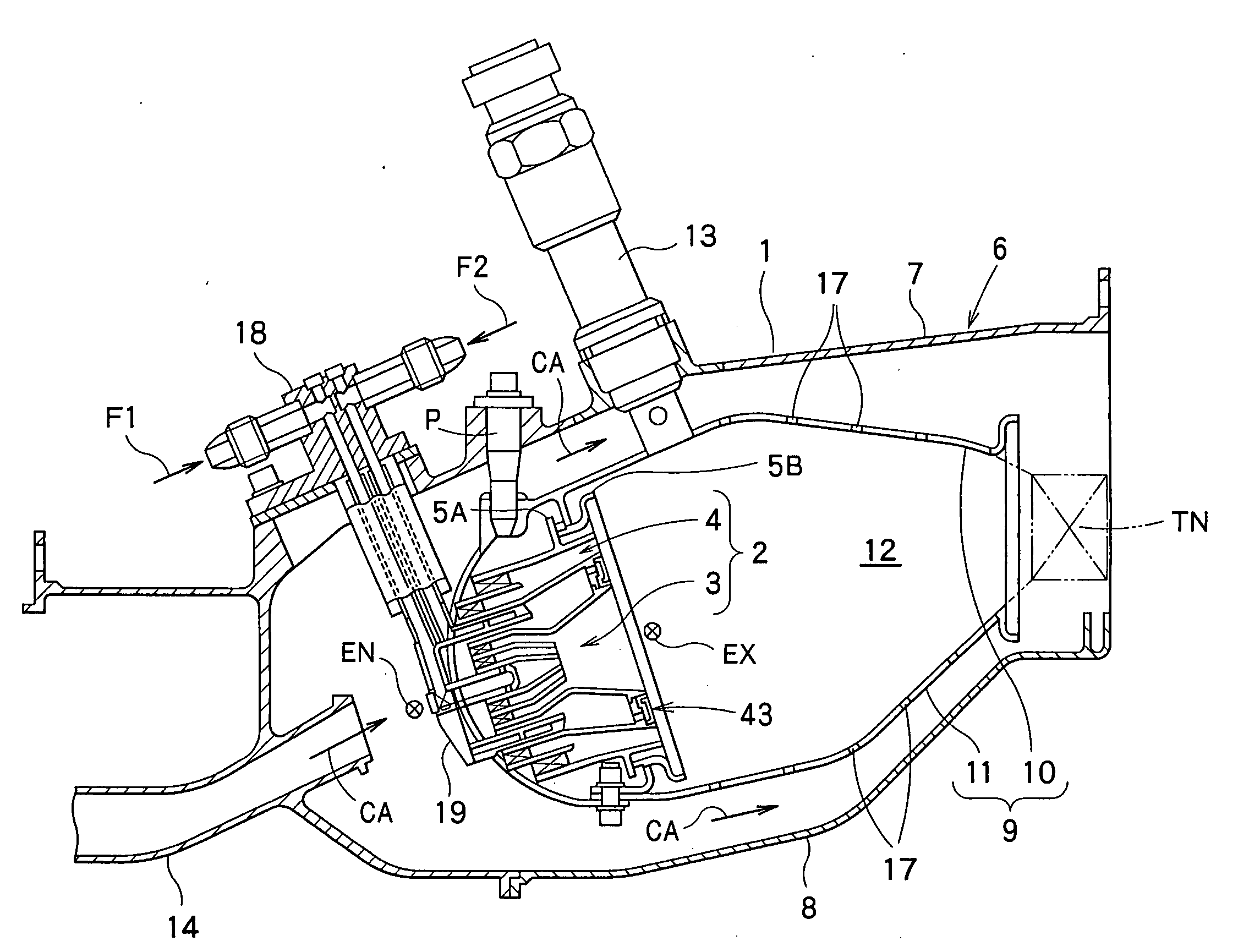
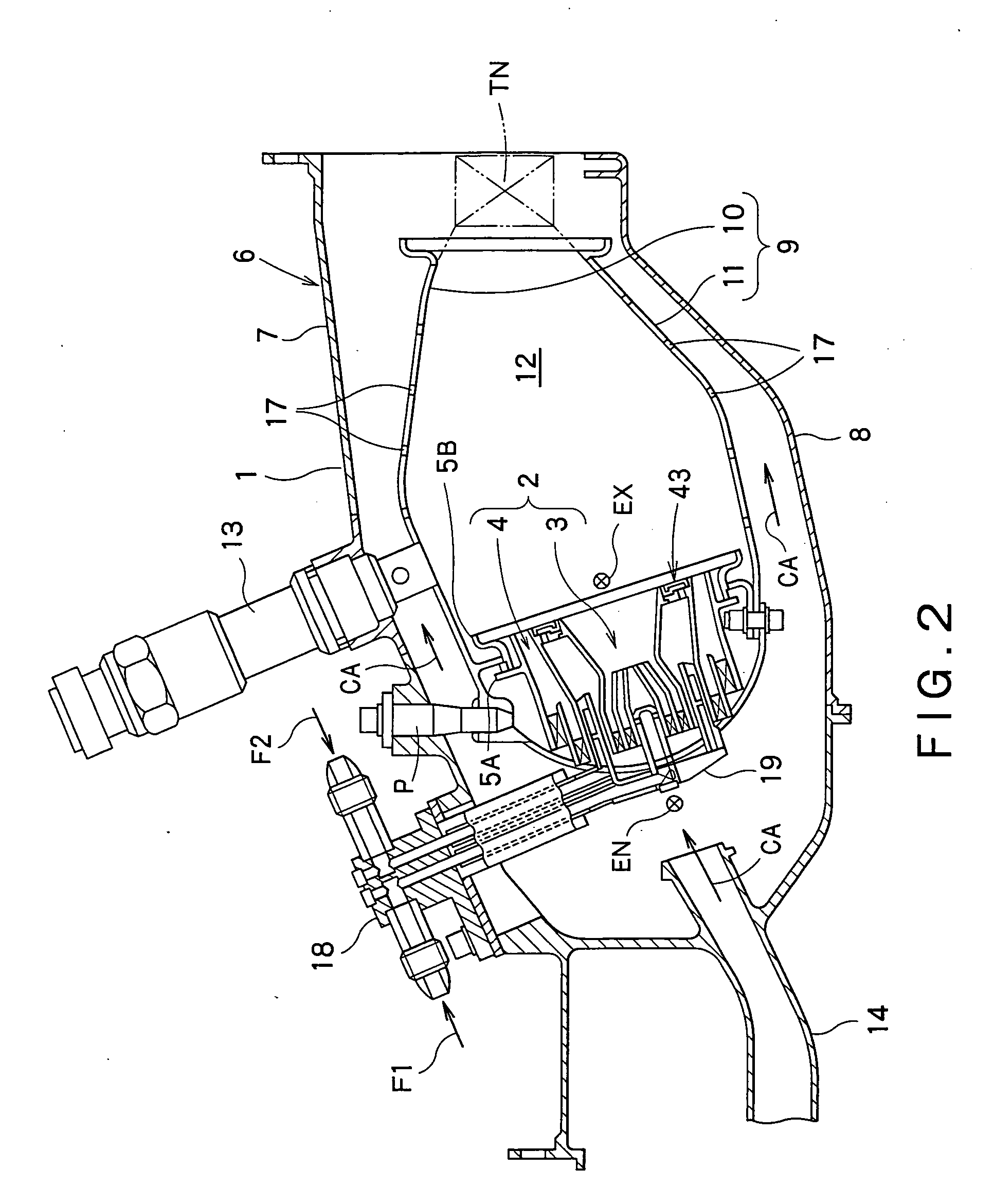
[0022]In this invention, it is preferred that the fuel spray portion includes a fuel atomizing portion configured to atomize the fuel, and a diffusion passage portion disposed downstream of the fuel atomizing portion, the diffusion passage portion having a spreading trumpet-like shape and being configured to diffuse the fuel and the air. With this configuration, since the mixture of the fuel and air can be injected into the combustion chamber while well spreading due to the diffusion passage portion having a spreading trumpet-like shape, the mixture can be well combustible, thus enhancing the stability of combustion in the diffusion combustion region.
[0023]As mentioned above, according to the combustor for use in the gas turbine engine of this invention, the diffusion combustion region and the pre-mixture combustion region can be separated from each other due to the separation portion disposed between the fuel spray portion and the pre-mixture supply portion. Therefore, mixing of the great amount of air supplied from the pre-mixture supply portion with the diffusion combustion flame created by the fuel supplied from the fuel spray portion can be prevented, while starting the operation and / or operating under lower intensity combustion. Consequently, flame failure of the diffusion combustion flame caused by such air can be avoided, while the entire diffusion combustion region can be kept in a fuel concentration range suitable for stable combustion, thereby the ignition performance, flame holding performance and stability of combustion can be significantly enhanced under a lower intensity combustion mode.

