Method and Apparatus for Spectroscopic Measurements in the Combustion Zone of a Gas Turbine Engine

a gas turbine engine and combustion zone technology, applied in the direction of instruments, lighting and heating apparatus, machines/engines, etc., can solve the problems of difficult arrangement in the operating environment, difficult to interpret data even if, and extremely difficult to measure, so as to improve the reflectivity

Active Publication Date: 2008-11-27
ONPOINT TECHNOLOGIES LLC
View PDF55 Cites 50 Cited by
  • Summary
  • Abstract
  • Description
  • Claims
  • Application Information

AI Technical Summary

Benefits of technology

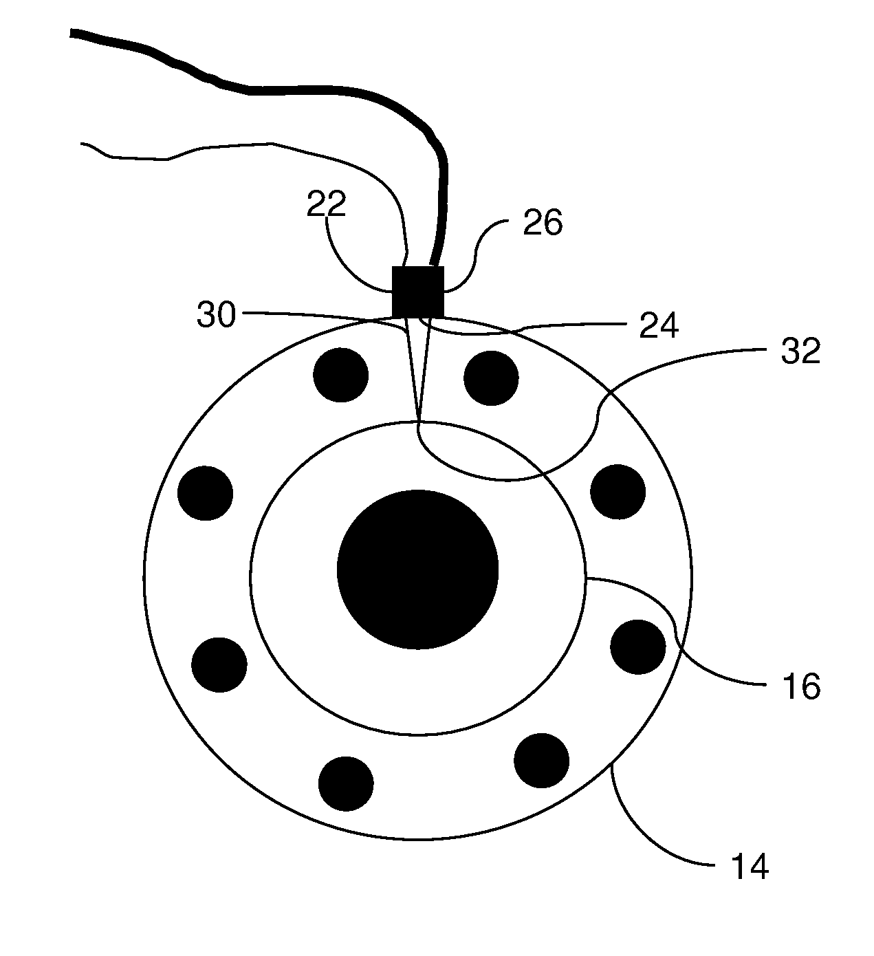
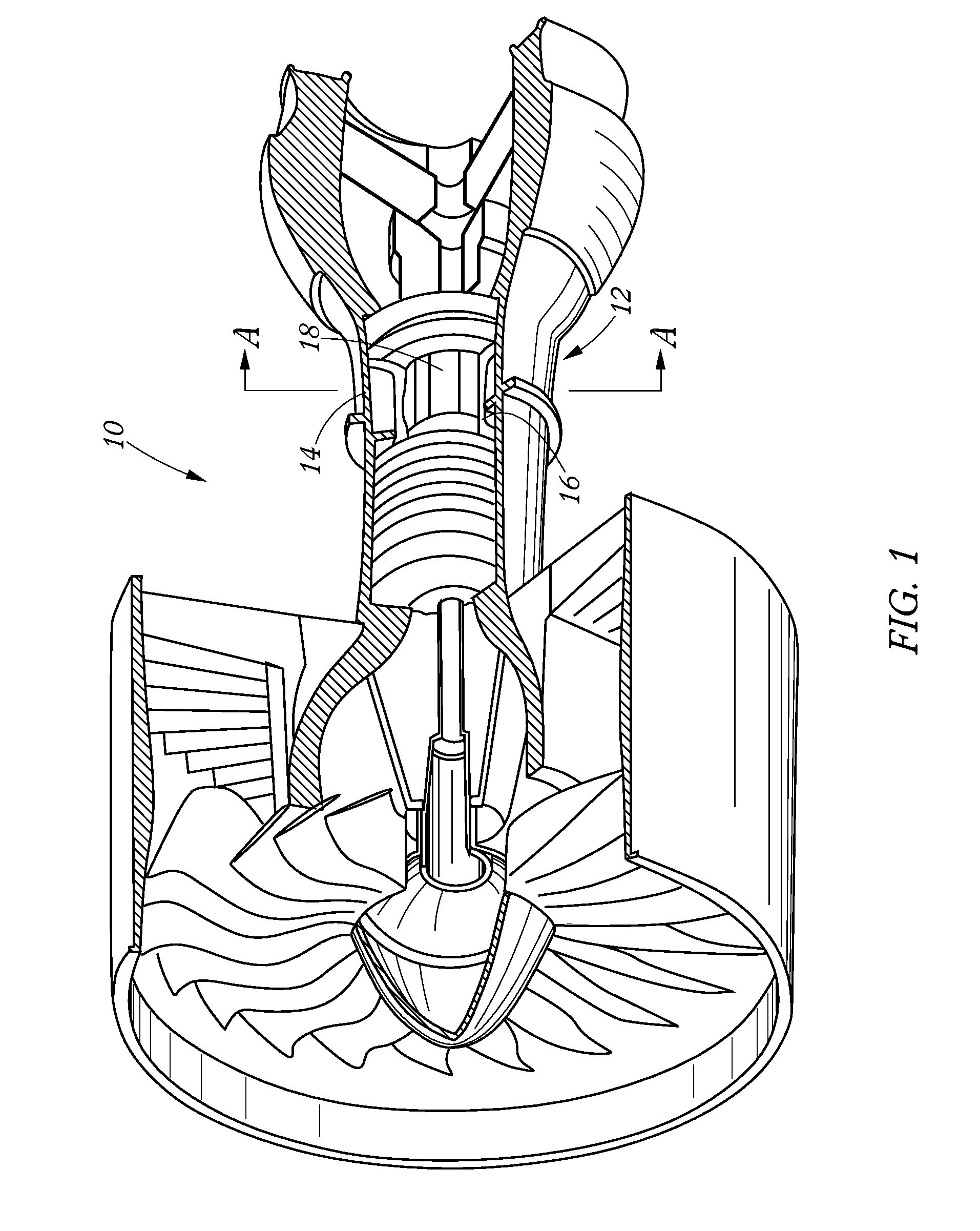
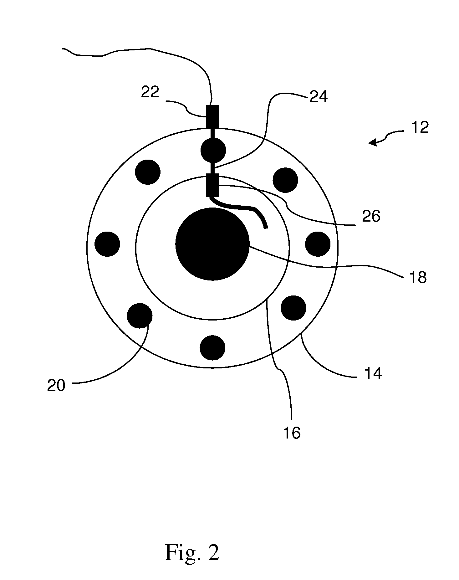
[0017]A first aspect of the invention is a method for measuring combustion properties within a combustion zone of a gas turbine engine, the combustion zone being defined between an inner and outer casing. The method comprises transmitting a beam from a transmit optic optically coupled to a port in the outer casing off a portion of the inner casing and receiving a portion of the beam reflected off the inner casing with a receiving optic optically coupled to a port in the outer casing. The transmit optic and the receiving optic may be optically coupled to the same port and the port may be a preexisting borescope port provided in the outer casing by the engine manufacturer to observe a turbine blade during servicing. The transmitting step may include transmitting a beam comprising a plurality of discrete multiplexed wavelengths. In such an embodiment, the method may further include demultiplexing

Problems solved by technology

While monitoring combustion properties in gas turbine engines would appear to have many potential benefits, making the measurements has proven extremely difficult.
The difficulty stems from two major sources.
First, the high-pressure and temperature of the combustion zone (30-40 bar, 2200 K) creates an environment in which normal spectral features are highly distorted, leading to difficulty in interpreting data even if it can be obtained.
Second, making such measurements in an operating engine requires optical access; that is, a penetration or penetrations in the engine casing through which one can direct a laser beam over a line of sight.
Th

Method used


Image

  • Method and Apparatus for Spectroscopic Measurements in the Combustion Zone of a Gas Turbine Engine
  • Method and Apparatus for Spectroscopic Measurements in the Combustion Zone of a Gas Turbine Engine
  • Method and Apparatus for Spectroscopic Measurements in the Combustion Zone of a Gas Turbine Engine

Examples


example

[0028]The following example is provided for illustrative purposes only and is not intended to limit the scope of the invention.

[0029]Data was collected from a transmitting / receiving pair of optics associated with a portion of an inner casing. In this example, the portion of the inner casing which the beam was directed to had been bead-blasted, which produces a higher degree of scattering than a typical inner casting of an engine would provide. Four wavelengths were multiplexed onto a single mode fiber, collimated and then directed by a transmit optic onto the bead blasted portion of the inner casing. The receiving optic was positioned to catch the specular reflection from the portion of the inner casing. FIG. 7 is a table setting forth the reflecting data collected. The multiplexed wavelength beams were at the following wavelengths: 1=1348 nm; 2=1376 nm; 3=1394 nm and 4=1559 nm. These wavelengths were chosen as being useful for measuring combustion species such as water (H2O), carbo...


PUM


Abstract

A method for measuring combustion parameters within a combustion zone of a gas turbine engine, the combustion zone being defined between an inner and outer casing. The method comprises transmitting a beam from a transmit optic optically coupled to a bore in the outer casing off a portion of the inner casing and receiving a portion of the beam reflected off the inner casing with a receiving optic optically coupled to a bore in the outer casing. An apparatus for practicing the method comprises a laser generating a beam and a transmitting/receiving optics pair, the transmitting/receiving optics pair being configured for operative association with a port in an outer casing of a gas turbine engine, whereby the transmitting/receiving optics are in optical communication by reflecting the beam off a portion of an inner casing.

Description

TECHNICAL FIELD[0001]The present invention is directed toward a method and apparatus for monitoring and control of a combustion process, and more particularly toward a method and apparatus for spectroscopic measurements in the combustion zone of a gas turbine engine.BACKGROUND OF THE INVENTION[0002]Laser-based spectroscopic instruments have been implemented in a variety of environments to extract measurement data. Laser-based measurement apparatus can be implemented in situ and offer the further advantage of high speed feedback suitable for dynamic process control. One technique for measuring combustion species such as gas composition, temperature and other combustion parameters (collectively, “combustion properties”) utilizes Tunable Diode Laser Absorption Spectroscopy (TDLAS). TDLAS is typically implemented with diode lasers operating in the near-infrared and mid-infrared spectral regions. Suitable lasers have been extensively developed for use in the telecommunications industry a...

Claims


Application Information

Patent Timeline
IPC IPC(8): F02C9/28F02C7/22G01N21/27
CPCF01D21/003F05D2260/80G01M15/14F02C9/28
Inventor SAPPEY, ANDREW D.MASTERSON, BERNARD PATRICKHOFVANDER, HENRIK
Owner ONPOINT TECHNOLOGIES LLC
Why Eureka
Try Eureka