Anti-Fogging Device and Anti-Fogging Viewing Member

a viewing member and anti-fogging technology, applied in the direction of heater elements, vehicle maintenance, heating element shapes, etc., can solve the problems of reducing the adhesion of the viewing member, so as to reduce the thickness and reduce the heat capacity. , the effect of high adhesion

Active Publication Date: 2008-11-27
MAN INNOVATIONS LTD
View PDF26 Cites 40 Cited by
  • Summary
  • Abstract
  • Description
  • Claims
  • Application Information

AI Technical Summary

Benefits of technology

[0041]A further advantage of the present invention is that the device is separated from the visor and thus the heating element is required to heat only the flexible sheet of the device, and not the visor. The flexible sheet typically has a much lower thickness than the visor, and thus a lower heat capacity than the visor. Thus, the power required by the heating element to heat the flexible sheet is typically lower than that required by heating elements mounted in contact with, or within, a visor.
[0042]The device preferably includes terminal portions for the heater element. These terminal portions may be connected to a power supply via known electrical connectors.
[0043]Preferred and / or optional aspects of the invention are set out below with respect to other aspects of the invention. These may be combined with the first aspect of the invention or with any preferred and / or optional feature of the first aspect of the invention.
[0044]In a second aspect, the present invention provides a kit for modifying a viewing member including an anti-fogging device according to the first aspect.
[0045]Preferably, the anti-fogging device has a backing sheet for covering the adhesive element. In use, the backing sheet may be removed from the adhesive element before application of the device to the viewing member. Thus, the kit may allow the adhesive to remain covered (and therefore retain a high level of adhesibility) until just before use of the device. The kit may therefore provide a simple DIY application of the device using a peel and stick approach.
[0046]The kit may include one or more electrical leads for connection to one or more respective terminal portions of the heater element track. The electrical leads may terminate in one or more suitable plug members for attachment to a power source. Typically, the device is switched on or off by physically attaching the device to the power supply (e.g. by pushing a jack plug into a power supply socket). The kit may further include power indication means for indicating when power is being supplied to the device. The indication means may, for example, be a visual indication means such as an LED.

Problems solved by technology

Fogging of such viewing members may occur due to condensation of water vapour in breath.
This may dangerously restrict the vision of the user / wearer.
The transparent heating films of the prior art have the disadvantage that they must be very thin to be transparent enough to allow a user to see through them.
This may require a high voltage, which is not desirable.
Furthermore, the heating elements of the prior art are liable to be damaged (e.g. by overheating or scratching) to the extent that the heating functionality of the element may be impaired.
This necessitates costly replacement of the visor or other viewing member.
Such accessories do not, therefore, prevent the condensation of water on the surface but instead modify the nature of the condensed water to reduce fogging.
A further problem with such accessories is that, by definition, the active surface must be exposed.
Consequently, there is a serious risk that the active surface with be scratched or abraded during use, reducing its effectiveness in reducing fogging.

Method used


Image

  • Anti-Fogging Device and Anti-Fogging Viewing Member
  • Anti-Fogging Device and Anti-Fogging Viewing Member
  • Anti-Fogging Device and Anti-Fogging Viewing Member

Examples


Embodiment Construction

[0065]The preferred embodiments of the invention will first be described with reference to a device for reducing or preventing fogging of a visor of a motorcycle helmet.

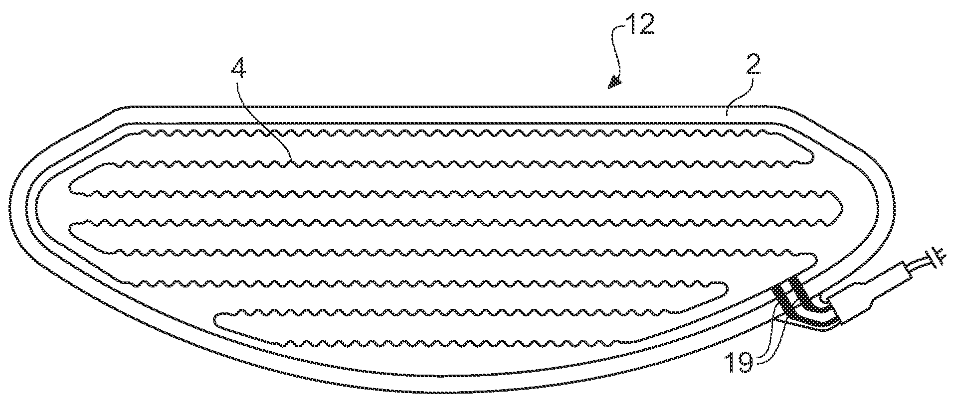
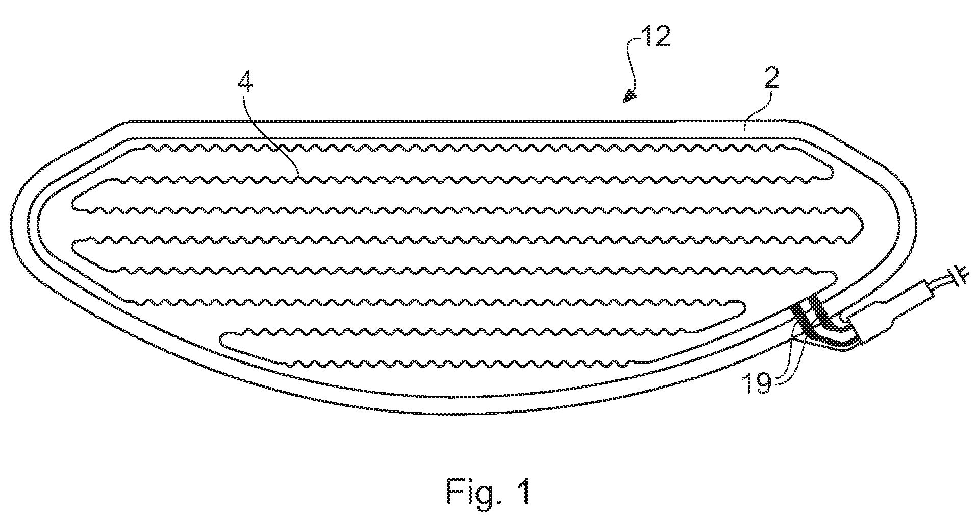
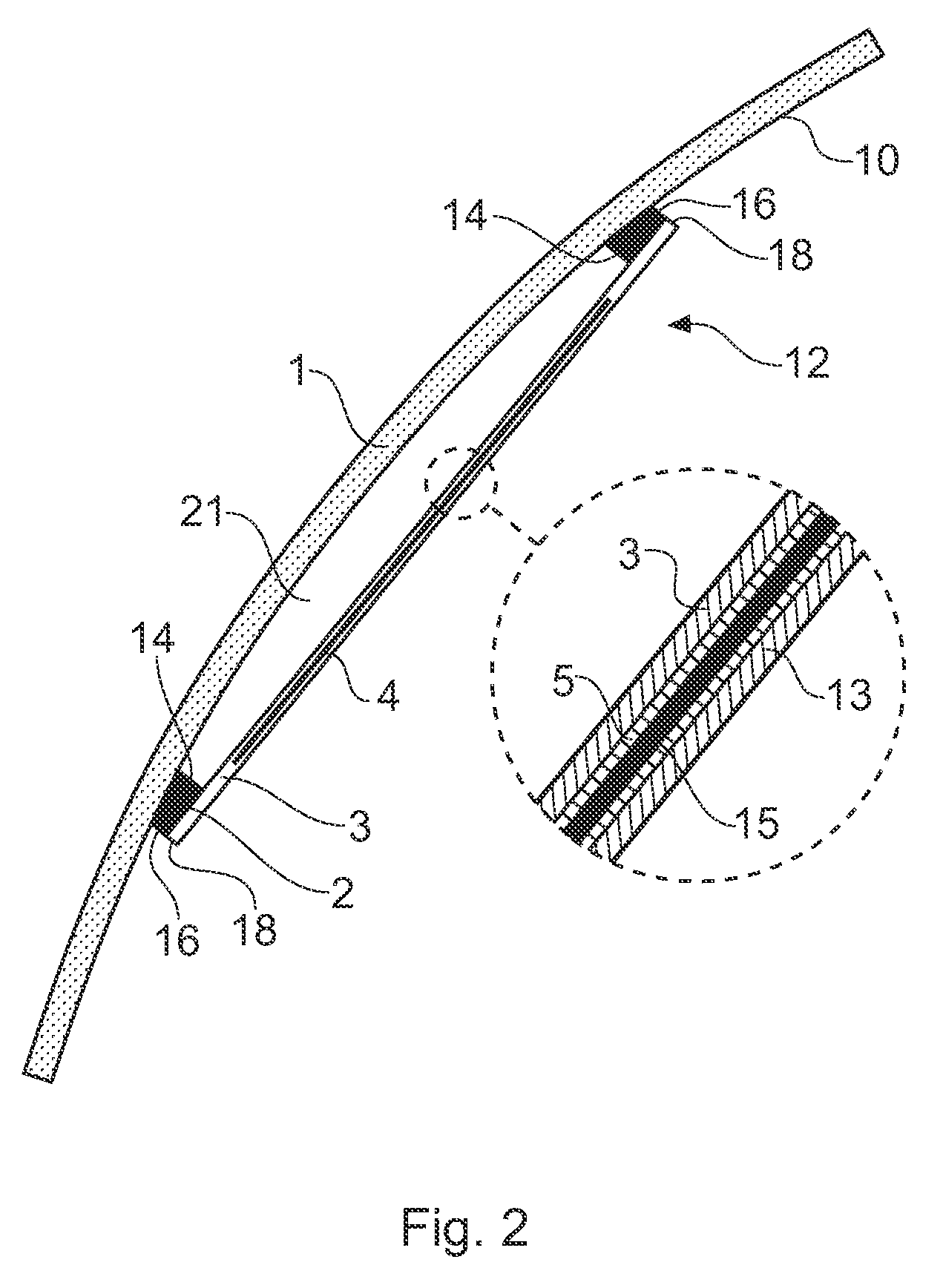
[0066]FIG. 1 shows a plan view of an anti-fogging device 12 of the present invention, for use on a motorcycle visor. The anti-fogging device 12 has a continuous adhesive pad 2 disposed at its perimeter. This adhesive pad is the preferred form of the adhesive element discussed above. The outer edges of the continuous adhesive pad are coterminous with the outer edges of the device.

[0067]The device has a heating element 4 which is in the form of a continuous track having a meandering pattern so that adjacent portions of the track are separated by a distance of between 0.5-2 cm, typically about 1 cm, at the vision area of the viewing member. The element is adapted to provide a power density of typically 36-108 watts per square foot. The element resistance may be selected according to the application, in order to provide ...


PUM


Abstract

An anti-fogging device has a substantially transparent or optically clear plastic layer with a heater element formed of etched metallic foil bonded to it. The device has an adhesive element disposed at the periphery of the device for sticking to a viewing member such as a motorcycle helmet visor, surgical mask or rear windscreen for a convertible car, to leave a gap between the heater element and the viewing member.

Description

BACKGROUND TO THE INVENTION[0001]1. Field of the Invention[0002]The present invention relates to devices for reducing or removing fogging of viewing members such as visors, windscreens and the like.[0003]2. Related Art[0004]It is known to heat viewing members such as motorbike helmet visors or car windscreens (windshields) in order to prevent or remove fogging (or misting) caused by the condensation of water on the cold surface of the viewing member. Typically, heat is provided to the viewing member either from a flow of heated air or by direct heating, e.g. via a resistive heater element carrying an electric current.[0005]Fogging of such viewing members may occur due to condensation of water vapour in breath. This may dangerously restrict the vision of the user / wearer.[0006]CH 636251 discloses a heatable visor. Resistive heating wires are located between two panes of the visor.[0007]GB-A-2401772 discloses a heated visor for a motorbike helmet with an electric heating element embedd...

Claims


Application Information

Patent Timeline
Patent Type & Authority Applications(United States)
IPC IPC(8): B60L1/02A42B3/24B60S1/02H05B3/84
CPCA42B3/245B60S1/026H05B2203/014H05B2203/017F21S45/60A42B3/24
Inventor BIDDELL, MICHAEL PHILIP
Owner MAN INNOVATIONS LTD
Why Eureka
Try Eureka