

Motor Controller
- Summary
- Abstract
- Description
- Claims
- Application Information
AI Technical Summary
Benefits of technology
Problems solved by technology
Method used
Image

Examples
first embodiment
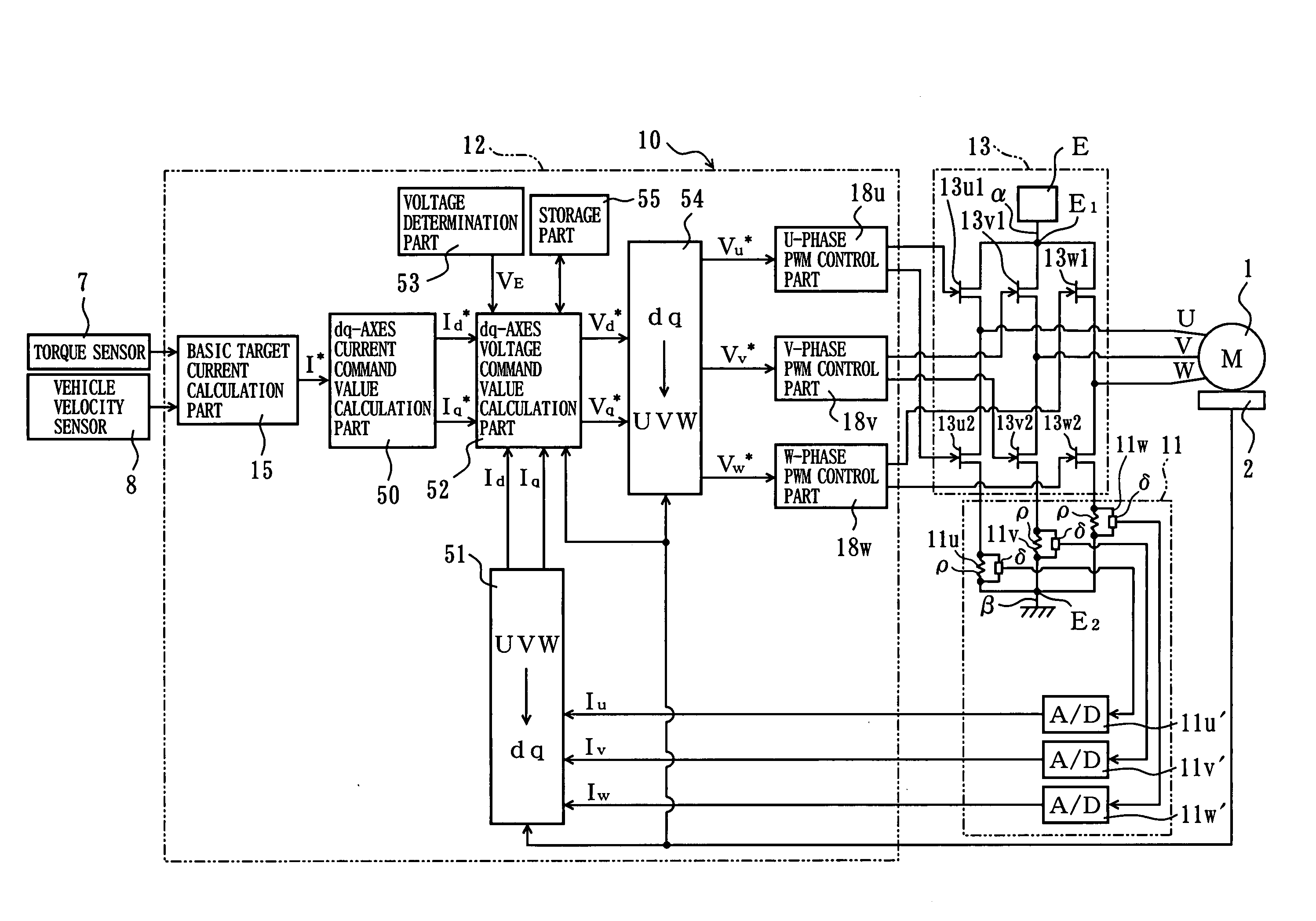
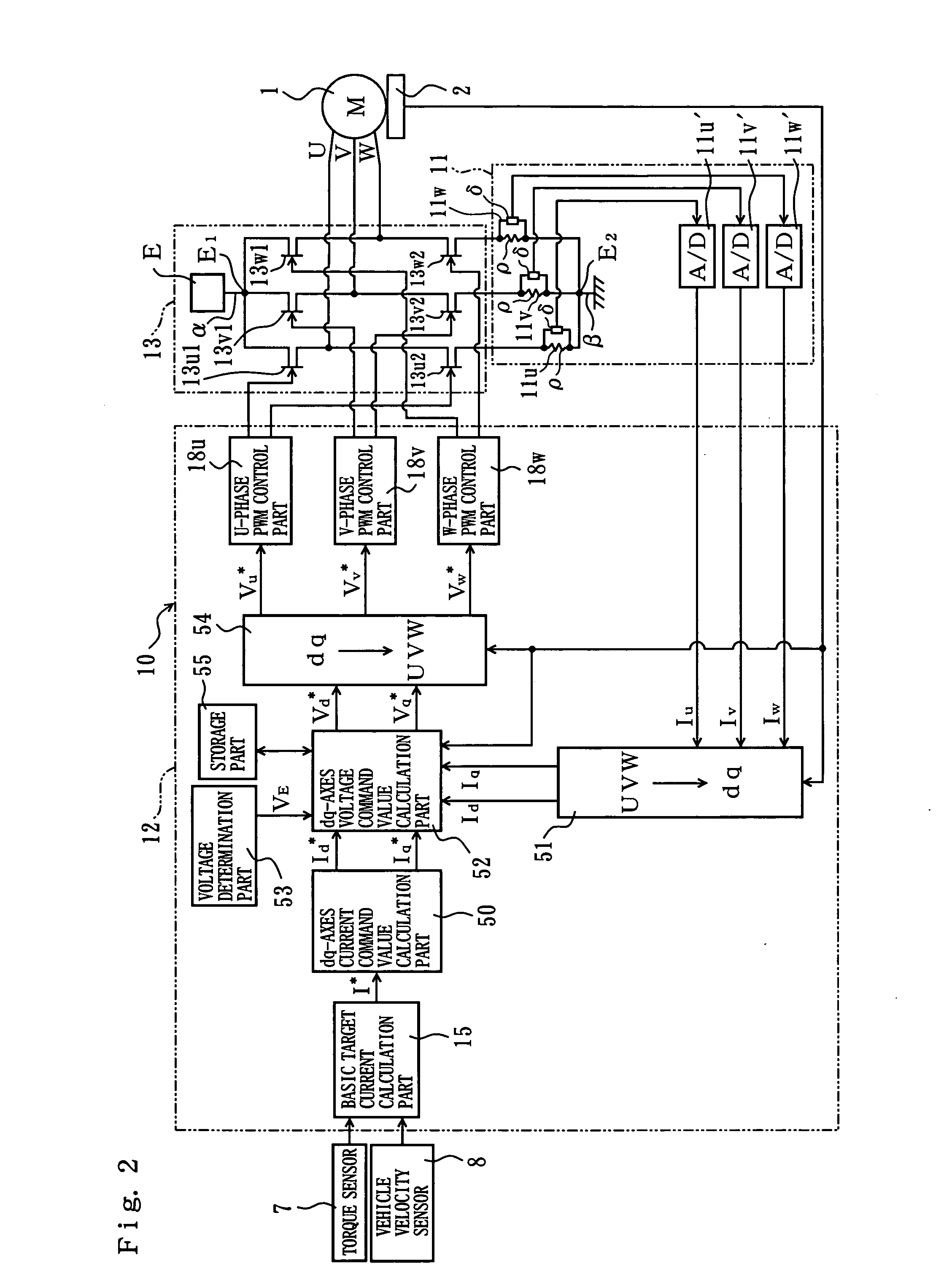
[0027]FIG. 2 is a function block diagram of the controller 10 of the The resolver 2, a torque sensor 7 that detects the steering torque transmitted by the steering shaft 103 and a vehicle velocity sensor 8 that detects the vehicle velocity are connected to the controller 10. The controller 10 has a current determination part 11, a signal processing part 12 and a drive part 13. The drive part 13 has a pair of U-phase MOS-FET 13u1, 13u2, a pair of V-phase MOS-FET 13v1, 13v2 and a pair of W-phase MOS-FET 13w1, FET13w2 as switching elements arranged in a power supply line to the motor 1. The FETs 13u1, 13u2, 13v1, 13v2, 13w1, 13w2 constitute an inverter circuit, and are switched on and off by PWM control signals to open-loop control the output of the motor 1 via the inverter circuit.
[0028]The current determination part 11 determines U-phase current value Iu, V-phase current value Iv and W-phase current value Iw, which are values of current flowing in the three-phase coils as values of ...
second embodiment
[0048]The flowchart of FIG. 7 shows a control procedure with the controller 10 of the second embodiment for the motor 1.
[0049]First, the detected values by the resolver 2, the torque sensor 7, the vehicle velocity sensor 8, the current detectors 11u, 11v, 11w, and the voltage determination part 53 are read (step S101), and the basic target current value I* is calculated based on the detected torque and vehicle velocity (step S102). The d-axis current command value Id* and q-axis current command value Iq* corresponding to the basic target current value I* are calculated (step S103), the d-axis current value Id and q-axis current value Iq corresponding to the detected phase current values Iu, Iv, Iw and rotation positions of the rotor 1b are calculated (step S104), the d-axis target applied voltage value Vd is calculated by the PI calculation of the difference between the calculated d-axis current command value Id* and the calculated d-axis current value Id, and the q-axis target appl...
third embodiment
[0058]In the third embodiment, the PWM control parts 18u, 18v, 18w serve as the signal generating part for generating the PWM control signals according to the respective phase voltage command values Vu*, Vv*, Vw*.
[0059]The flowchart of FIG. 9 shows a control procedure with the controller 10 of the third embodiment for the motor 1. First, the detected values by the resolver 2, the torque sensor 7, the vehicle velocity sensor 8, the current detectors 11u, 11v, 11w and the voltage determination part 53 are read (step S301), and the basic target current value I* is calculated based on the detected torque and vehicle velocity (step S302). The respective phase current command values Iu*, Iv*, Iw* corresponding to the basic target current value I* are calculated (step S303), the speed electromotive forces Eu, Ev, Ew, which are determined based on the rotation positions of the rotor 1b detected in time series, are calculated (step S304), the respective phase equivalent resistance values Ru,...
PUM
 Abstract
Description
Claims
Application Information