Fuel cell system and method of starting operation of fuel cell system
Inactive Publication Date: 2008-11-27
HONDA MOTOR CO LTD
View PDF15 Cites 3 Cited by
Summary
Abstract
Description
Claims
Application Information
AI Technical Summary
This helps you quickly interpret patents by identifying the three key elements:
Problems solved by technology
Method used
Benefits of technology
[0013]The present invention has been made to solve the above problems, and an object of the present invention is to provide a fuel cell system and a method of starting operation of the fuel cell system i
Problems solved by technology
In this case, at the time of starting operation of the system, if the fuel cell is operated at a low temperature, power generation of the fuel cell may not be performed efficiently.
In general, in the system, in a state where the output voltage of the fuel cell is equal to the terminal voltage of the battery (the fuel cell is directly coupled to the battery), it is no longer possible to further decrease t
Method used
Image
Click on the blue label to locate the original text in one second.
Reading with bidirectional positioning of images and text.
Examples
first embodiment
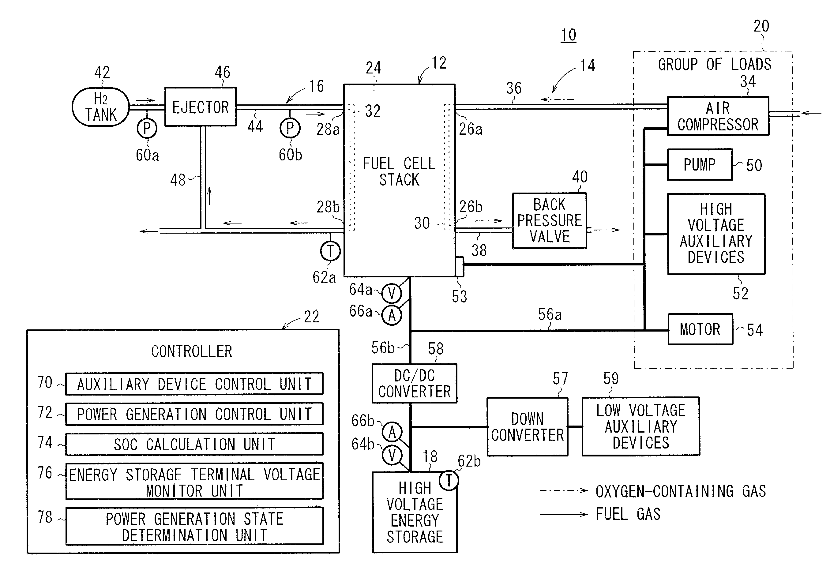
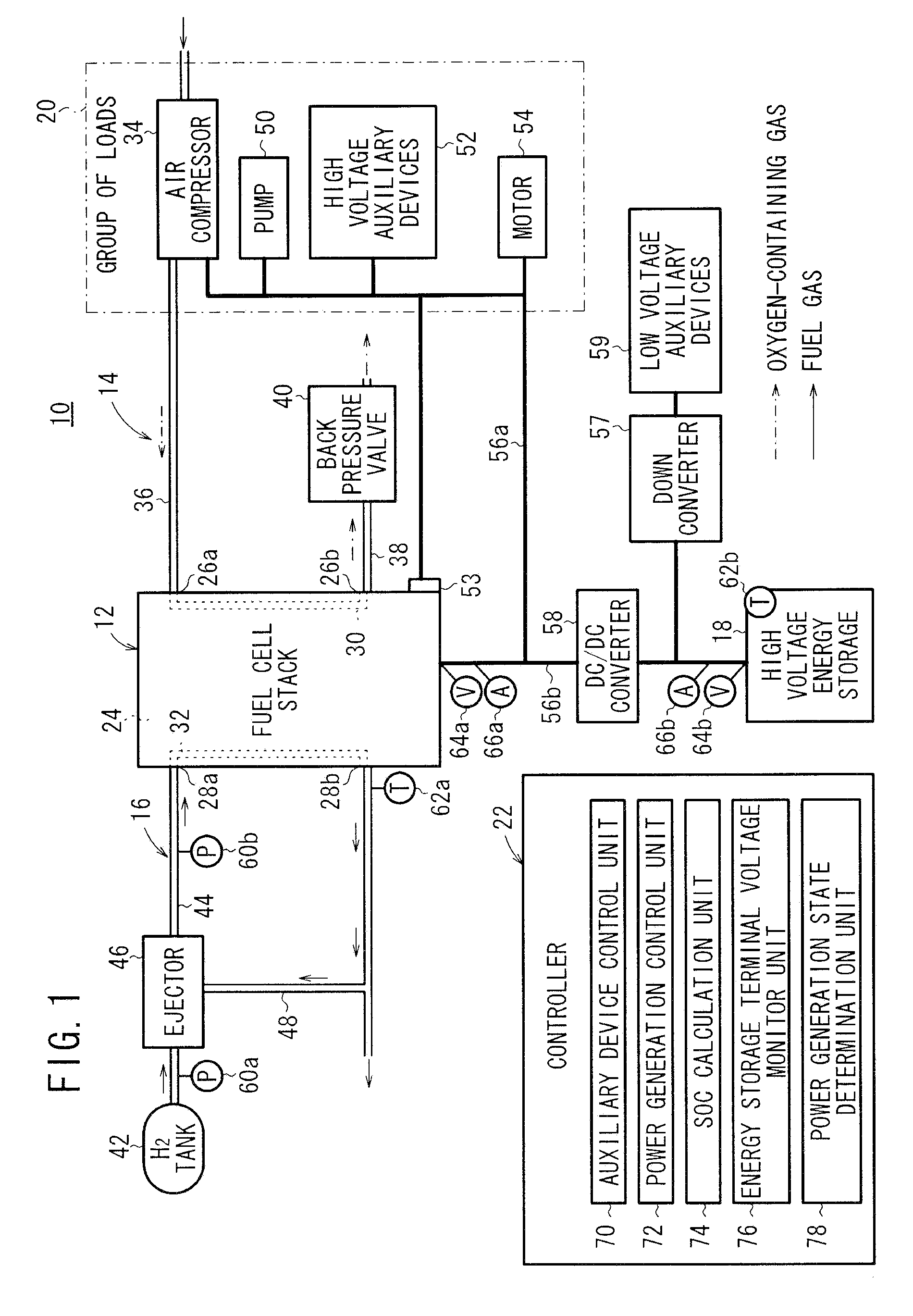
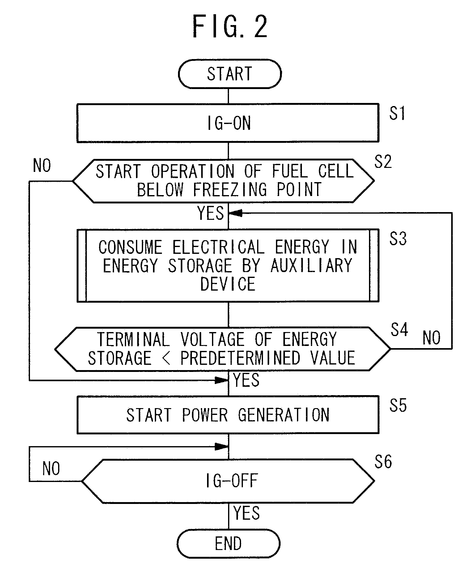
[0039]Next, operation of the fuel cell system 10 will be descried in connection with a method of starting operation of a fuel cell system according to the present invention with reference to a flow chart in FIG. 2.
[0040]Firstly, when an ignition (not shown) of the fuel cell system 10 is turned on, (step S1), the process proceeds to step S2, and the power generation state determination unit 78 determines whether operation of the fuel cell stack 12 is started at a temperature below the freezing point or not.
[0041]As shown in FIG. 3, in comparison with the normal temperature, the I-V characteristics of the fuel cell 24 (current-voltage characteristic) are significantly poor at low temperature, in particular, below the freezing point. Thus, in step S2, if it is determined that operation of the fuel cell stack 12 is started at a temperature below the freezing point (YES in step S2), i.e., if it is determined that operation of the fuel cell stack 12 will not be brought into a steady state...
second embodiment
[0056]Next, a method of starting operation of the fuel cell stack 12 will be described with reference to a flow chart in FIG. 6.
[0057]In the second embodiment, the control device 22 has functions of a warming up completion determining device for determining whether warming up of the high voltage energy storage 18 has been completed or not, and a voltage boosting restriction device for restricting increase in the voltage of the high voltage energy storage 18.
[0058]Firstly, after the ignition is turned on, processes before power generation of the fuel cell stack 12 is started (step S11 to step S15) are performed in the same manner as the steps S1 to S5 of the first embodiment.
[0059]Further, after power generation of the fuel cell stack 12 is started, the process proceeds to step S16 to determine whether it is necessary to restrict increase in the terminal voltage of the high voltage energy storage 18, e.g., based on whether warming up of the high voltage energy storage 18 has been co...
PUM
Abstract
A fuel cell system includes a fuel cell stack for power generation by electrochemical reactions of a fuel gas and an oxygen-containing gas, a high voltage energy storage capable of storing and discharging electrical energy generated by power generation of the fuel cell stack, and capable of being directly coupled to the fuel cell stack, a group of loads consuming at least electrical energy generated by the fuel cell stack or electrical energy discharged from the high voltage energy storage, and an auxiliary device control unit for reducing an amount of electrical energy remaining in the energy storage to a predetermined value by any of the group of loads, before starting power generation of the fuel cell stack.
Description
BACKGROUND OF THE INVENTION[0001]1. Field of the Invention[0002]The present invention relates to a fuel cell system including a fuel cell, an energy storage, and a group of loads. The fuel cell performs power generation by electrochemical reactions of reactant gases. The energy storage is capable of storing and discharging electrical energy generated by the fuel cell, and capable of being directly coupled to the fuel cell. The group of loads consume at least electrical energy generated by the fuel cell or electrical energy discharged from the energy storage. Further, the present invention relates to a method of starting operation of the fuel cell system.[0003]2. Description of the Related Art[0004]The fuel cell is a system for obtaining direct current electrical energy by electrochemical reactions of a fuel gas (chiefly hydrogen-containing gas) supplied to an anode and an oxygen-containing gas supplied to a cathode.[0005]For example, a polymer electrolyte fuel cell includes a power ...
Claims
Application Information
Patent Timeline
Application Date:The date an application was filed.
Publication Date:The date a patent or application was officially published.
First Publication Date:The earliest publication date of a patent with the same application number.
Issue Date:Publication date of the patent grant document.
PCT Entry Date:The Entry date of PCT National Phase.
Estimated Expiry Date:The statutory expiry date of a patent right according to the Patent Law, and it is the longest term of protection that the patent right can achieve without the termination of the patent right due to other reasons(Term extension factor has been taken into account ).
Invalid Date:Actual expiry date is based on effective date or publication date of legal transaction data of invalid patent.