Very Narrow Band Multipoint Communication System

a communication system and narrow band technology, applied in multiplex communication, frequency-division multiplex, instruments, etc., can solve the problems of inability to offer inherent performance advantages over conventional approaches to frequency or digital code hopping, and inability to achieve the inherent performance advantage of single channel in terms of channel bandwidth, so as to increase the gain, reduce transmission collisions, and increase the transmission range of transponders

Active Publication Date: 2008-11-27
MEEK THOMAS
View PDF5 Cites 15 Cited by
  • Summary
  • Abstract
  • Description
  • Claims
  • Application Information

AI Technical Summary

Benefits of technology

[0006]The present invention meets the needs described above in a very narrow band multipoint communication protocol suitable for use in an automatic meter reading (“AMR”) system that implements a frequency division multiplexing technique in addition to the interference limiting frequency or digital code hopping technique typically implemented by AMR systems. More specifically, the inventive very narrow band communication protocol divides each main channel of an interference limiting frequency or digital code hopping system into multiple sub-channels and applies frequency division multiplexing among the sub-channels. This allows each sub-channel to exhibit a very narrow band characteristic that allows the gain to be increased within the very narrow band, which in turn increases the transmission range of the transponders, such as a large number of geographically distributed meters. Because the mult

Problems solved by technology

Conventional AMR systems are bandwidth limited, however, by the number of channels implemented by the communication protocol, the width of the channels, and the available gain in view of the broadcast power restrictions.
Specifically, frequency or digital code hopping among the channels permits narrow band communication protocol within the spread spectrum, but does not offer any inherent performance advantage over single channel in terms of channel bandwidth.
Conv

Method used


Image

  • Very Narrow Band Multipoint Communication System
  • Very Narrow Band Multipoint Communication System
  • Very Narrow Band Multipoint Communication System

Examples


Embodiment Construction

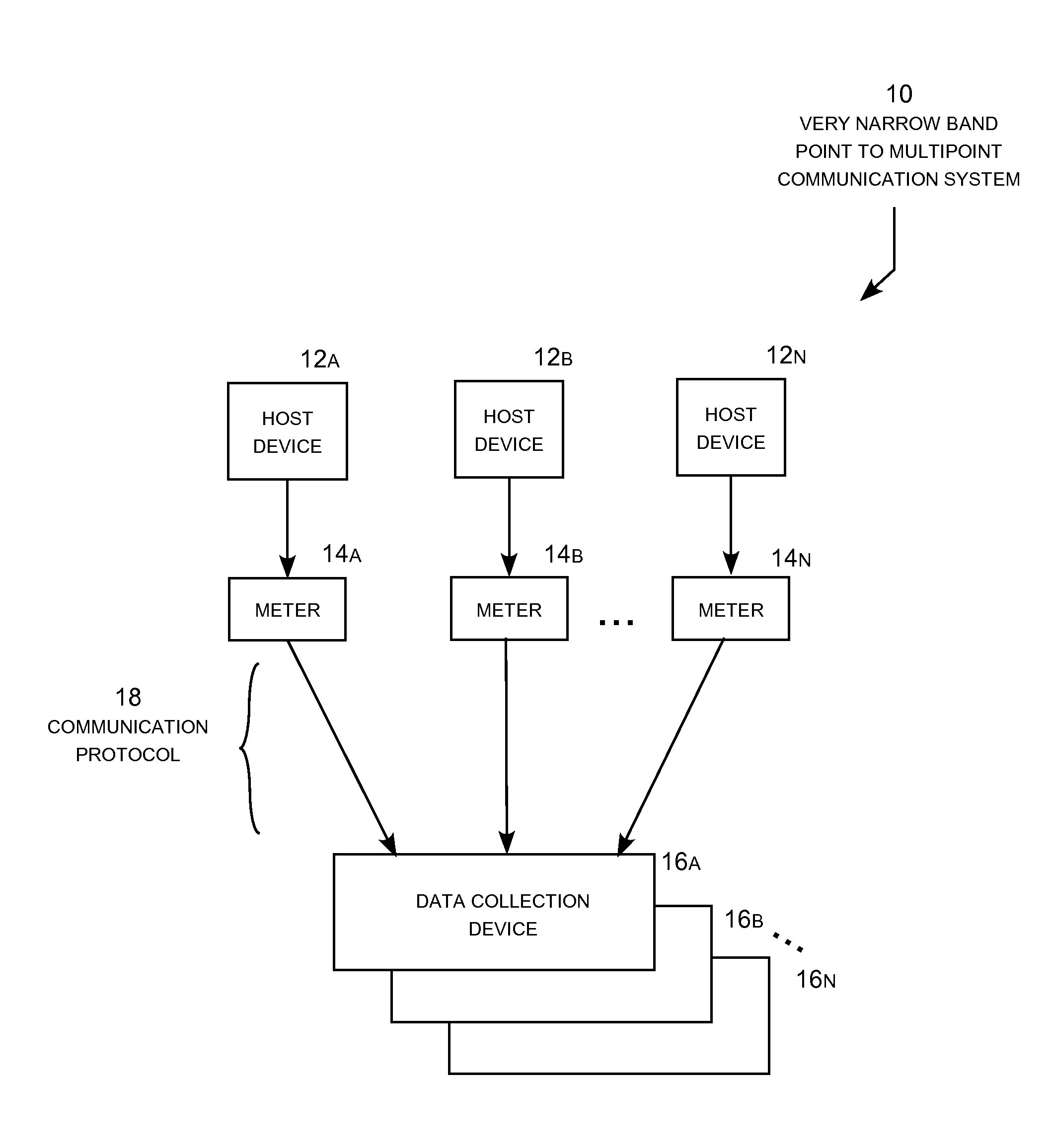
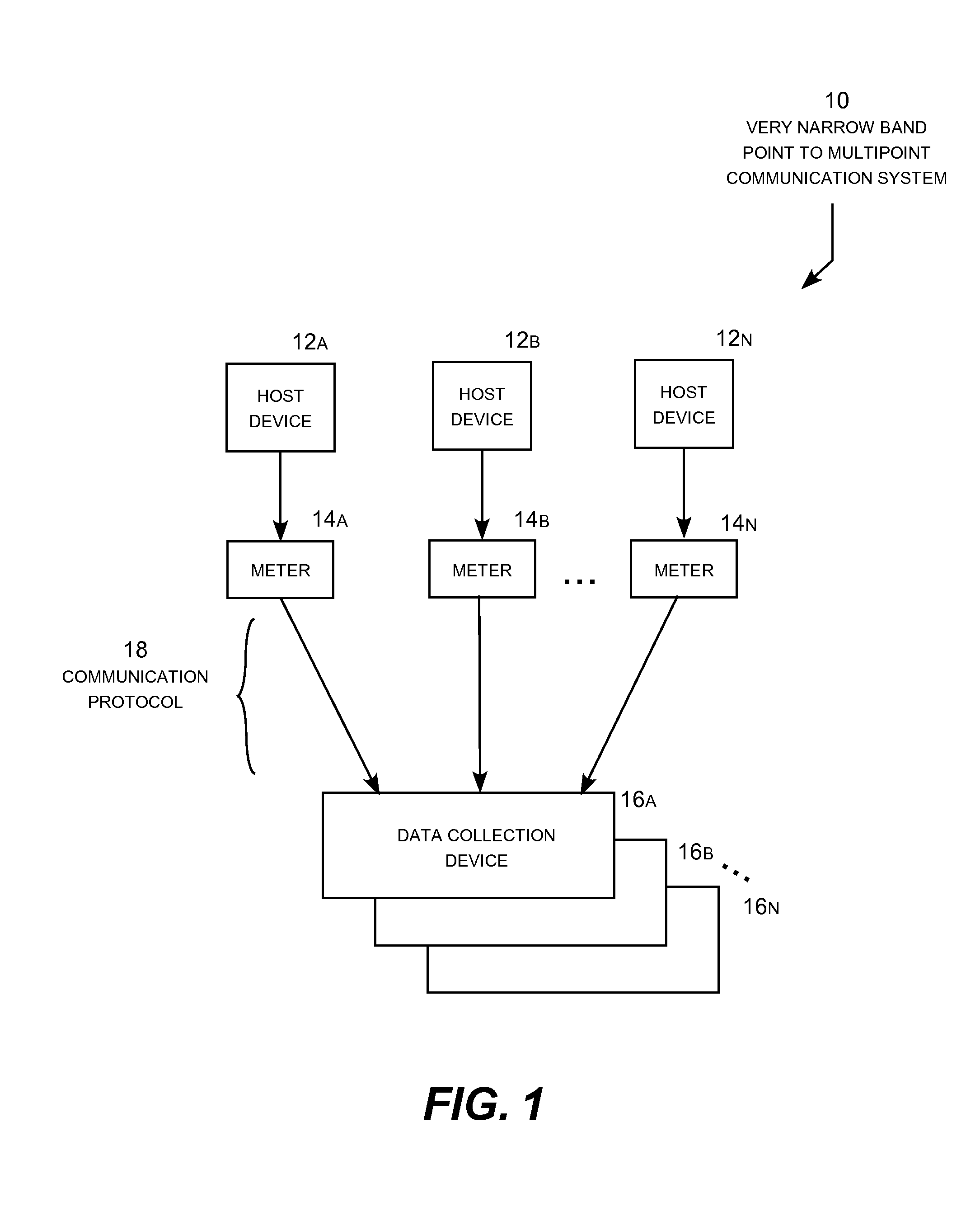
[0019]The present invention may be embodied in a very narrow band point to multipoint communication system that uses single or multi-channel transponders where the multipoint receiver, also referred to as a data collection device, is more advanced in its technology than the single point transmitters and receivers. The very narrow band communication system is particularly well adapted for use in an application characterized by a relatively large number of transponders that each transmit a small amount of data infrequently at low power. The illustrative very narrow band point-to-multipoint communication system described below is specifically designed for an automatic meter reading (“AMR”) system, but may be used in other applications having similar characteristics. The principle advantages of the very narrow band communication system are greater transmission range, greater packet bandwidth, and the ability to accommodate a much larger number of transponders per data collection device ...


PUM


Abstract

A very narrow band multipoint communication system suitable for use in an automatic meter reading (AMR) system having a communication protocol that divides each main channel of a frequency or digital code hopping system into multiple sub-channels and applies frequency division multiplexing among the sub-channels. Each sub-channel exhibits a very narrow band characteristic that allows gain increase to increases the transmission range of the meters. In addition, frequency division multiplexing among the sub-channels greatly increases the number of meters that can communicate on each main channel. The data collection device demodulates and decodes the multiplexed meter signals at an intermediate frequency with electronic circuitry. The resulting very narrow band AMR system exhibits greater transmission range, greater bandwidth and can accommodate a much larger number of meters per data collection device in comparison to conventional narrow band AMR system.

Description

REFERENCE TO RELATED APPLICATION[0001]This application claims priority to U.S. Provisional Patent Application Ser. No. 60 / 939,379 filed May 22, 2007 entitled “Multipoint Communication System,” which is incorporated herein by reference.TECHNICAL FIELD[0002]The present invention relates generally to multipoint communication systems and, more particularly, to an automatic meter reading system implementing a very narrow band communication protocol that divides an operational frequency band into main channels, implements interference limiting frequency or digital code hopping among the main channels, divides the main channels into sub-channels, and implements frequency division multiplexing among the sub-channels.BACKGROUND OF THE INVENTION[0003]Compared to other types of RF communication systems, automatic meter reading (“AMR”) systems are characterized by a relatively large number of meters that each transmit a relatively small amount of data infrequently at very low power. For example...

Claims


Application Information

Patent Timeline
IPC IPC(8): G08C15/02H04B1/707H04B1/713
CPCG01D4/002H04B1/715H04J13/00H04J13/0074Y02B90/241Y04S20/32Y04S20/30Y02B90/20
Inventor MEEK, THOMAS
Owner MEEK THOMAS
Why Eureka
Try Eureka