

Electro-optical device, driving circuit of electro-optical device, and electronic apparatus
a driving circuit and electrooptical technology, applied in the direction of electric digital data processing, instruments, computing, etc., can solve the problems of increasing the width of the so-called window frame outside the display area, increasing the cost, and complex circuitry for driving the capacitor lines. achieve the effect of simple circuitry
- Summary
- Abstract
- Description
- Claims
- Application Information
AI Technical Summary
Benefits of technology
Problems solved by technology
Method used
Image

Examples
third embodiment
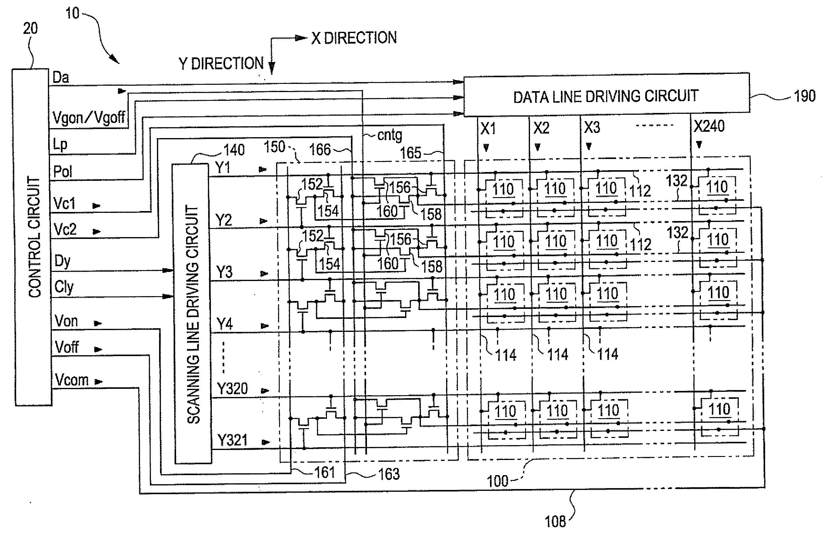
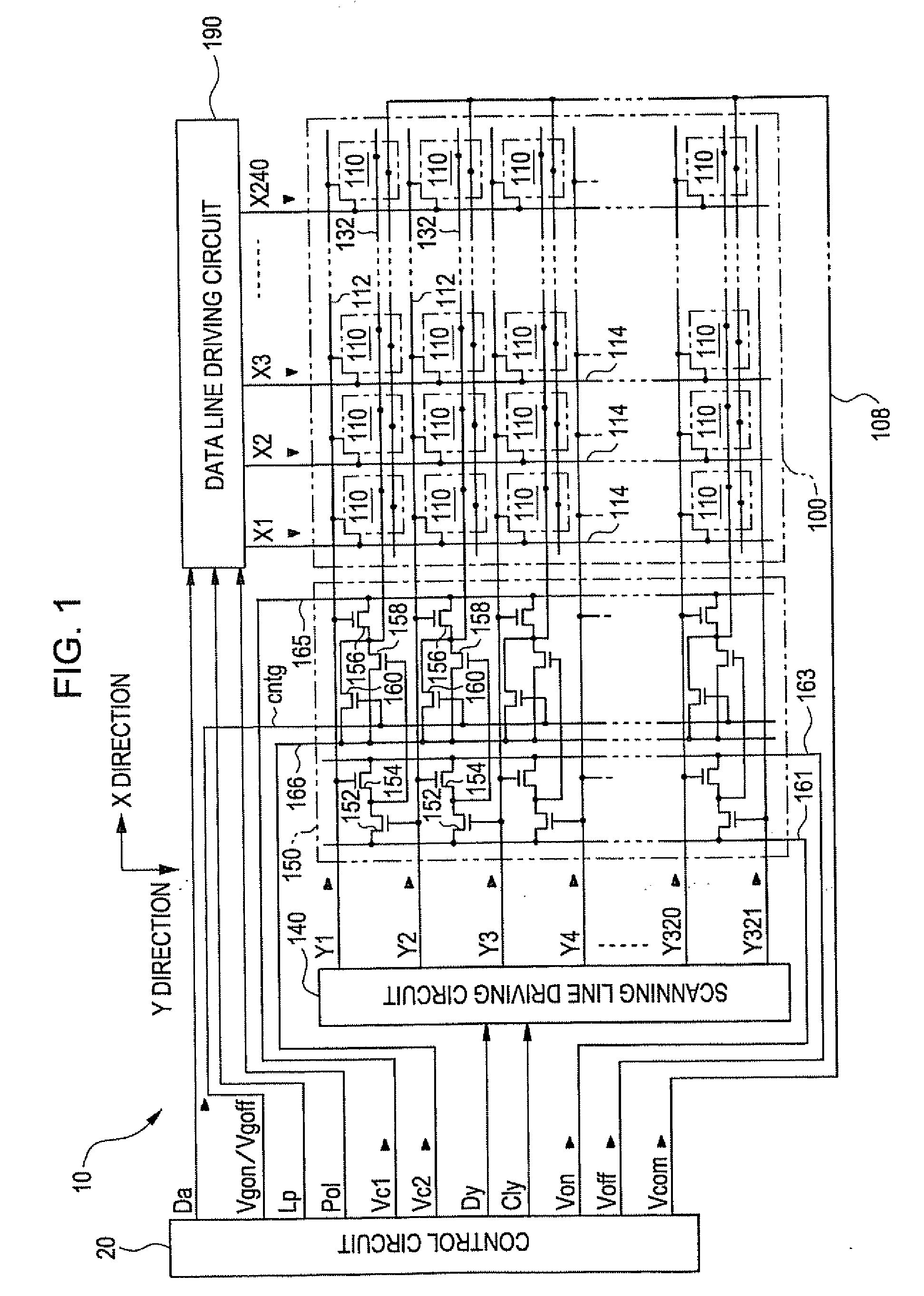
[0131]Next, a third embodiment according to the invention will be described. FIG. 10 is a block diagram that shows the configuration of an electro-optical device according to the third embodiment of the invention. As shown in the drawing, the electro-optical device 10 has a display area 100 and arranges a scanning line driving circuit 140, a capacitor line driving circuit 150 and a data line driving circuit 190 around the display area 100. The display area 100 is an area in which pixels 110 are arranged. In the present embodiment, 320 scanning lines 112 are provided to extend in a row direction (X) direction, while 240 data lines 114 are provided to extend in a column (Y) direction. Then, the pixels 110 are arranged at positions corresponding to intersections of the first to 320th scanning lines 112 and the first to 240th data lines 114. Thus, in the present embodiment, the pixels 110 are arranged in the display area 100 in a matrix of 320 rows by 240 columns. In addition, capacitor...
first application
and Modification of Third Embodiment
[0174]Note that, in this description, by holding the second capacitive signal Vc2 constant at the voltage Vsl, the voltage of the i-th capacitor line 132 is made unchanged in the n-th frame during which positive polarity writing is specified, while the voltage of the i-th capacitor line 132 is decreased by the voltage ΔV in the (n+1)th frame during which negative polarity writing is specified. Thus, the voltage of the pixel electrode 118, which has been written when the scanning signal Yi was at an H level, is decreased by the voltage ΔVpix. However, the configuration may be opposite to this. That is, as shown in FIG. 18, it is applicable that, by holding the second capacitive signal Vc2 constant at the voltage Vsh, the voltage of the i-th capacitor line 132 is made unchanged in a frame during which negative polarity is specified, while the voltage of the i-th capacitor line is increased by the voltage ΔV in a frame during which positive polarity ...
second application
and Modification of Third Embodiment
[0175]Furthermore, in this description, all the polarities written to the pixels in a period of one frame are uniform, and a surface in version mode in which the writing polarity is inverted once in every period of one frame; however, a scanning line inversion mode or a line inversion mode in which the writing polarity is inverted once in every line may be applied. In the case of scanning line inversion mode, the polarity specifying signal Pol, as shown in FIG. 19, is inverted once in every horizontal scanning period (H). When, between any adjacent frames, when a period during which the same scanning signal is at an H level (the same scanning line is selected) is focused, the polarity specifying signals Pol are inverted relative to each other. Furthermore, the first capacitive signal Vc1 becomes the voltage Vsl when the polarity specifying signal Pol is at an H level, and becomes the voltage Vsh when the polarity specifying signal Pol is at an L l...
PUM
 Abstract
Description
Claims
Application Information