
Apparatus for and method of displaying video signals

Inactive Publication Date: 2008-11-27
JVC KENWOOD CORP A CORP OF JAPAN
View PDF8 Cites 68 Cited by
  • Summary
  • Abstract
  • Description
  • Claims
  • Application Information

AI Technical Summary

Benefits of technology

[0007]In consideration of such requirements, an object of the present invention is to provide an apparatus for and a method of displaying video signals, capable of receiving video signals of different frame frequencies, converting any one of the received video signals into a video signal of higher frame frequency, and displaying the video signal of higher frame frequency on a display in high quality by fully utilizing the ability of the display. Another object of the present invention is to provide an apparatus for and a method of displaying video signals, capable of displaying the video signals at low power consumption and low heat generation.
[0008]Still another object of the present invention is to provide an apparatus for and a method of displaying video signals, capable of receiving video signals of different frame frequencies, converting any one of the received video signals into a video signal of higher frame frequency, and displaying the video signal of higher frame frequency on a display in high quality without flicker at low power consumption and low heat generation.
[0021]It is preferable that determining a second frame frequency for the input video signal determines as the second frame frequency a highest frame frequency that is suitable for the first frame frequency and does not exceed a maximum acceptable frame frequency of the display.
[0031]In this way, any one of the aspects of the present invention receives video signals of different frame frequencies, converts the frame frequency of a necessary one of the received video signals into a higher one, and displays the video signal of higher frame frequency on a display in high quality by fully utilizing the ability of the display at low power consumption and low heat generation.
[0032]Also, any one of the aspects of the present invention receives video signals of different frame frequencies, converts the frame frequency of a necessary one of the received video signals into a higher one, and displays the video signal of higher frame frequency on a display in high quality without flicker at low power consumption and low heat generation.

Problems solved by technology

A liquid crystal display employing a liquid crystal panel has a problem of afterglow when displaying a moving image.

Method used


Image

  • Apparatus for and method of displaying video signals
  • Apparatus for and method of displaying video signals
  • Apparatus for and method of displaying video signals

Examples


Embodiment Construction

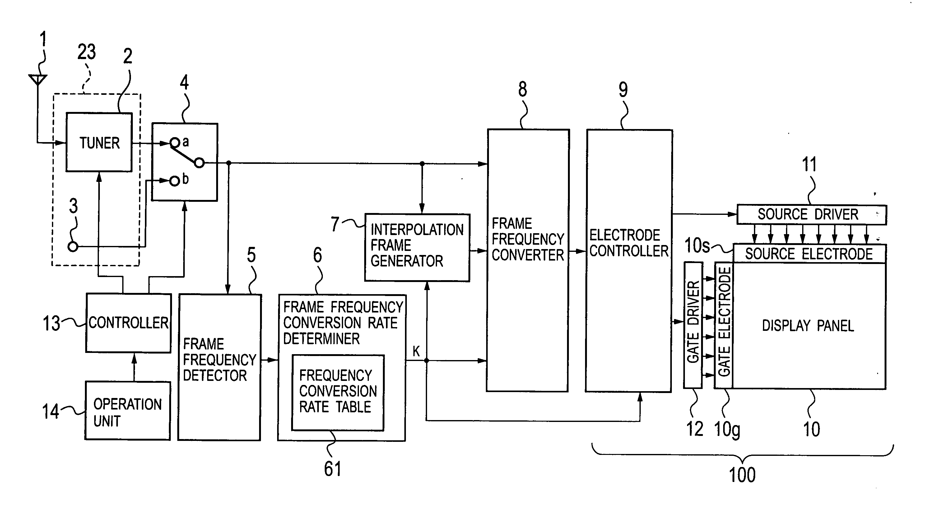
[0046]An apparatus for and a method of displaying video signals according to the present invention will be explained with reference to the accompanying drawings. FIG. 1 is a block diagram showing an apparatus for displaying video signals according to an embodiment of the present invention. In FIG. 1, an antenna 1 receives a television broadcast signal and supplies the same to a tuner 2. The tuner 2 may be an analogue tuner or a digital tuner. It may be a terrestrial-wave tuner or a satellite broadcast tuner. From the supplied signal, the tuner 2 demodulates the broadcast-wave signal of a required channel into a video signal having a predetermined frame frequency. An operation unit 14 is a set of operation buttons installed on the apparatus or a remote controller. With the operation unit 14, a user selects a desired channel, to send a channel switching signal to a controller 13. In response to the channel switching signal, the controller 13 selects the desired channel with the tuner ...


PUM


Abstract

An apparatus for displaying video signals includes an input source to receive video signals having different frame frequencies and provide an input video signal from among the received video signals, a frame frequency detector to detect, as a first frame frequency, the frame frequency of the input video signal, a determiner to determine a second frame frequency according to the first frame frequency and provide a frame frequency conversion rate, the second frame frequency being higher than the first frame frequency, an interpolation frame generator to generate interpolation frames according to the frame frequency conversion rate, and a frame frequency converter to convert the input video signal into a video signal having the second frame frequency by interpolating the generated interpolation frames between original frames of the input video signal.

Description

BACKGROUND OF THE INVENTION[0001]1. Field of the Invention[0002]The present invention relates to an apparatus for and a method of converting an input video signal having an original frame frequency into a video signal having a frame frequency higher than the original frame frequency and displaying the converted video signal on a display such as a liquid crystal display.[0003]2. Description of Related Art[0004]A liquid crystal display employing a liquid crystal panel has a problem of afterglow when displaying a moving image. One technique of resolving the problem is to convert an input video signal having an original frame frequency into a video signal whose frame frequency is higher than the original frame frequency and display the converted video signal on the display. An example of this technique is disclosed in Japanese Unexamined Patent Application Publication No. 2005-148521. This publication discloses an apparatus that converts an input video signal having a frame frequency of...

Claims


Application Information

Patent Timeline
IPC IPC(8): H04N5/46H04N3/14
CPCG09G3/20G09G3/3611G09G3/3614G09G5/005G09G2320/0247G09G2320/0261G09G2320/08G09G2320/106G09G2330/021G09G2340/0435H04N7/0132H04N7/014G02F1/133G09G3/36G09G5/02
Inventor SHISHIDO, TOMOYUKIAIBA, HIDEKI
Owner JVC KENWOOD CORP A CORP OF JAPAN
Learn More