Pattern formation method and pattern formation apparatus, exposure method and exposure apparatus, and device manufacturing method

Active Publication Date: 2008-11-27
NIKON CORP
View PDF15 Cites 10 Cited by
  • Summary
  • Abstract
  • Description
  • Claims
  • Application Information

AI Technical Summary

Benefits of technology

[0023]With this apparatus, in the measurement zone whose position in at least a first direction is different from the exposure zone, a plurality of marks on the object are detected by the mark detection system that has a plurality of detect

Problems solved by technology

Therefore, when the number of sample shot areas increases, the measurement takes a considerable amount of time, which could lead to the reduction in throughput of the entire exposure a

Method used


Image

  • Pattern formation method and pattern formation apparatus, exposure method and exposure apparatus, and device manufacturing method
  • Pattern formation method and pattern formation apparatus, exposure method and exposure apparatus, and device manufacturing method
  • Pattern formation method and pattern formation apparatus, exposure method and exposure apparatus, and device manufacturing method

Examples


Embodiment Construction

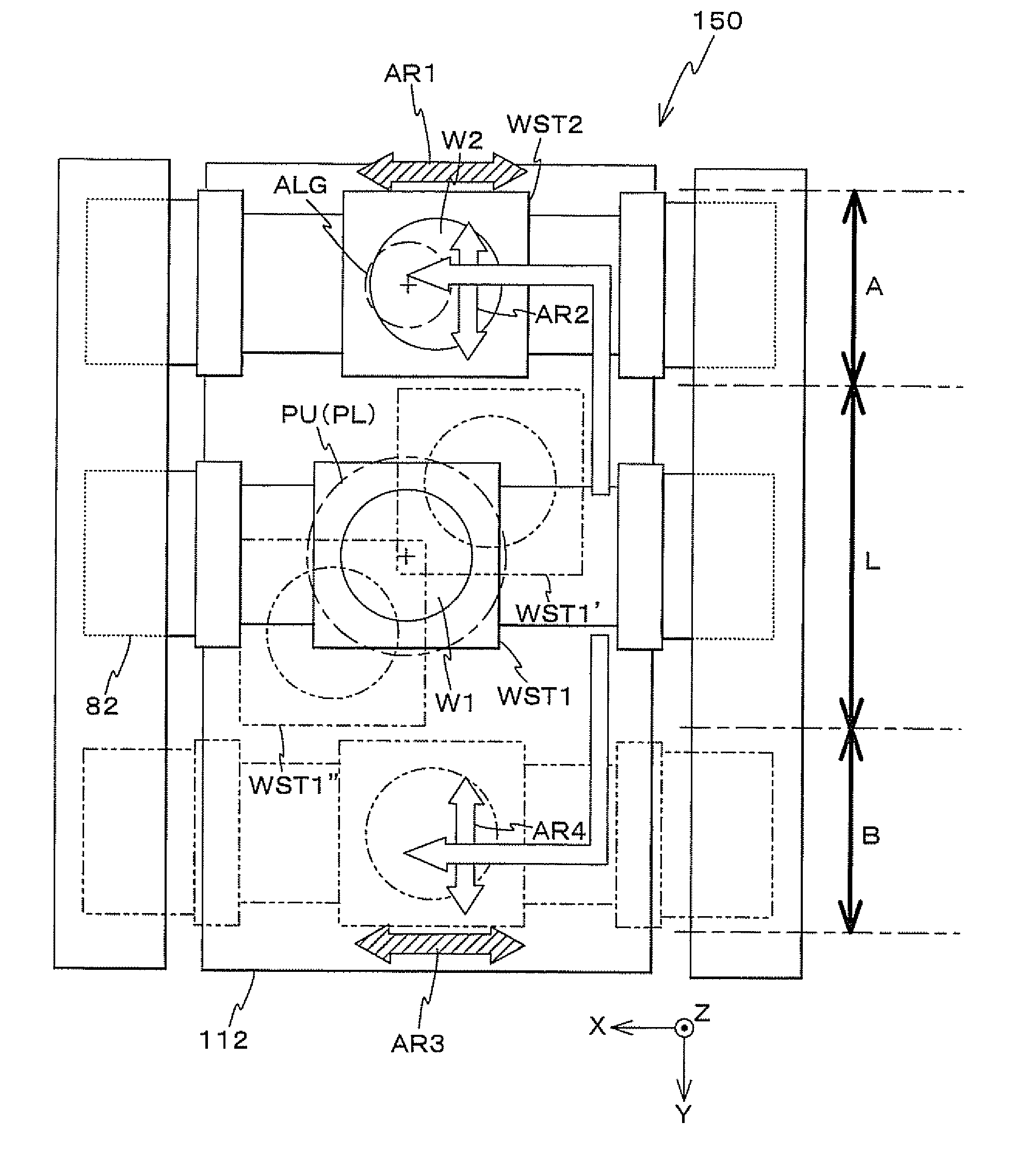
[0038]An embodiment of the present invention will be described below, referring to FIGS. 1 to 11.

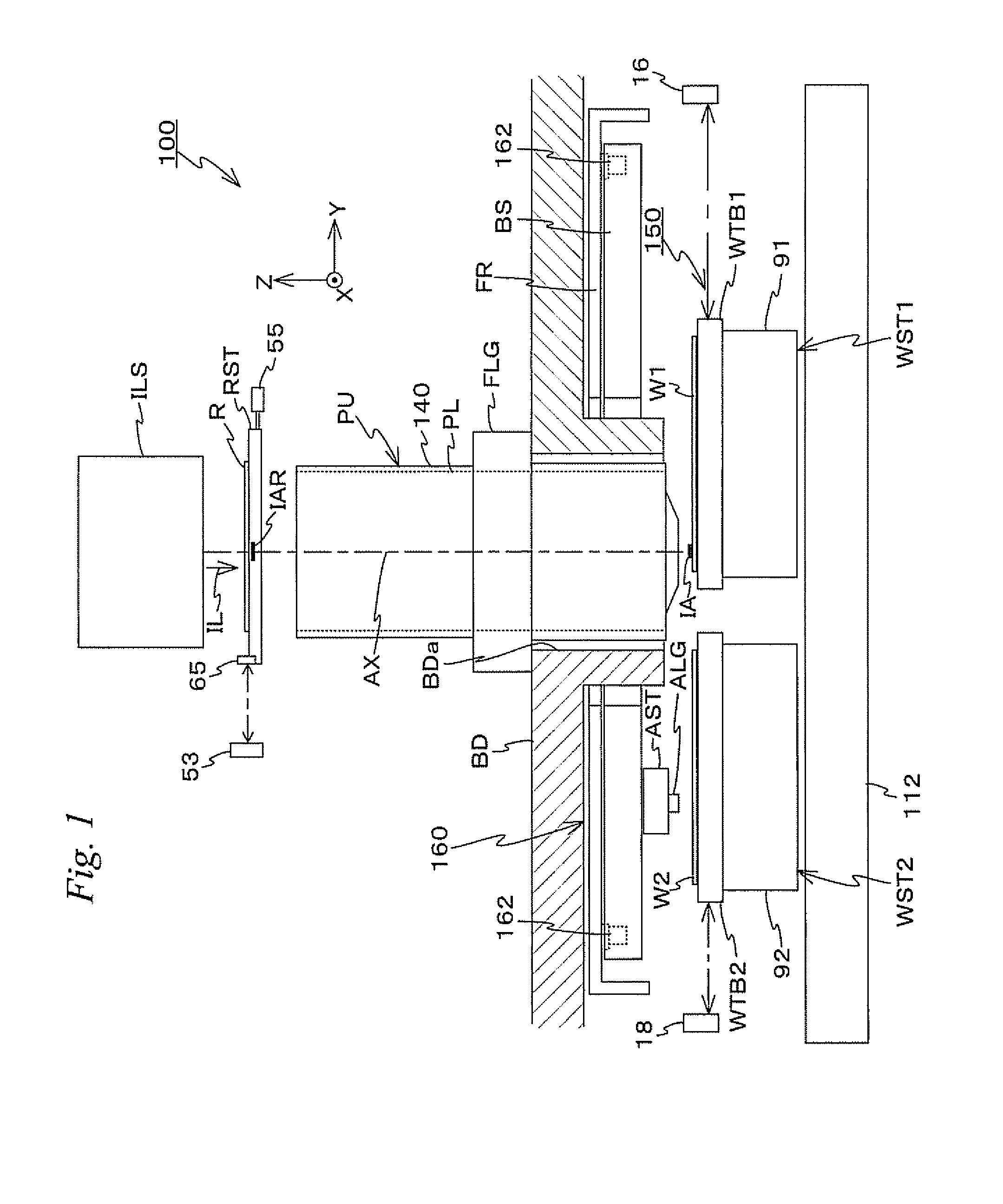
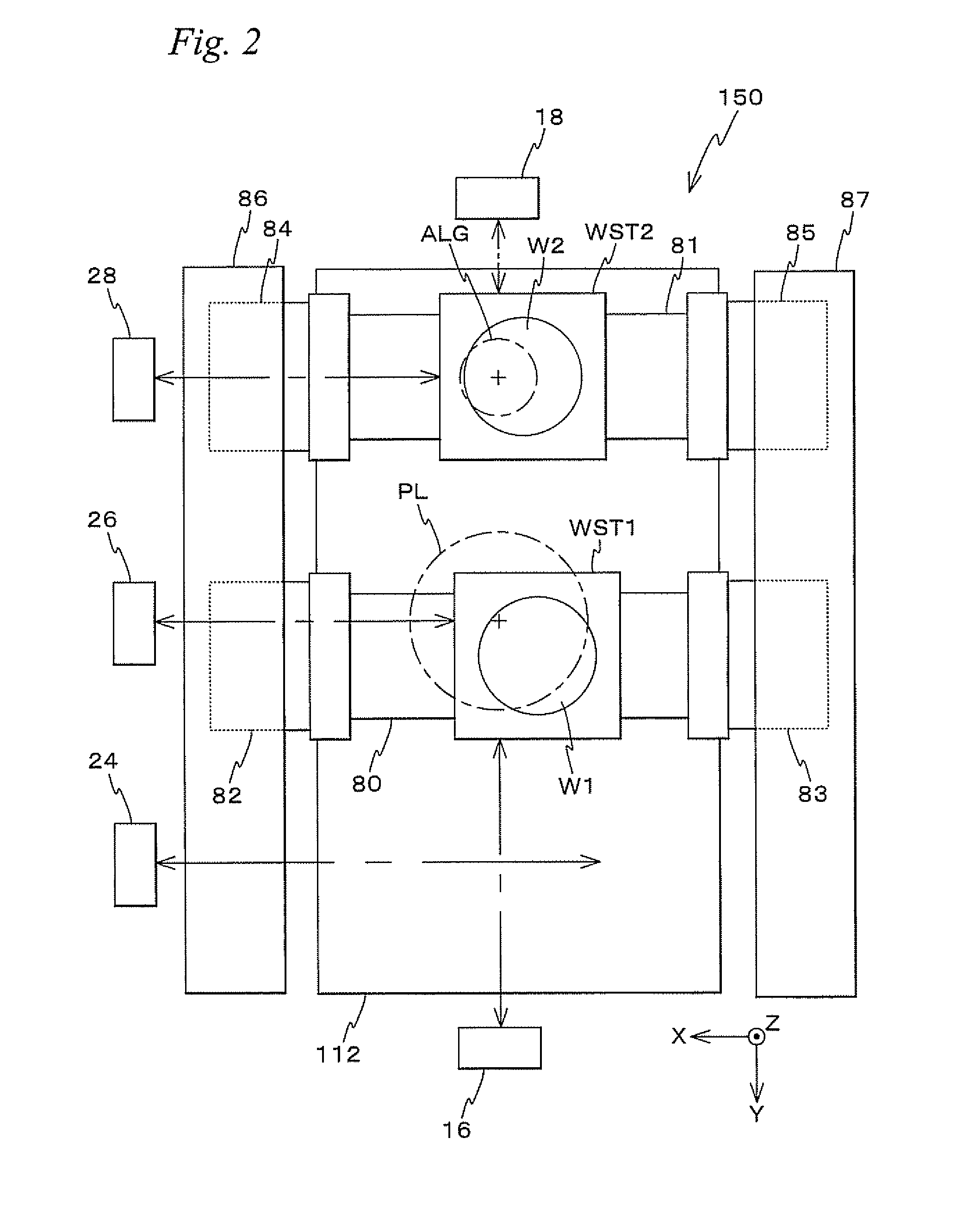
[0039]FIG. 1 schematically shows a configuration of an exposure apparatus 100 related to the embodiment. Exposure apparatus 100 is a scanning exposure apparatus based on a step-and-scan method, that is, a so-called scanner.

[0040]Exposure apparatus 100 includes an illumination system ILS that irradiates an illumination light for exposure (hereinafter, referred to as an illumination light or an exposure light) IL to an illumination area IAR on a reticle R, a reticle stage RST that holds reticle R, a projection unit PU including a projection optical system PL that projects illumination light IL emitted from reticle R onto a wafer W, a stage device 150 that includes wafer stages WST1 and WST2 on which wafers W1 and W2 are mounted respectively, an alignment system ALG, a drive device (hereinafter, referred to as an alignment system stage device) 160 serving as an actuator that drives alignmen...


PUM


Abstract

In a measurement zone that is spaced apart in a Y-axis direction from an exposure zone that is located immediately below a projection unit, a detection area of an alignment system is moved in the Y-axis direction and a plurality of marks are sequentially detected, and therefore a movement distance of wafer stages in the Y-axis direction when performing the mark detection can be decreased compared with the case where only the wafer stages are moved while fixing the alignment system and mark detection is performed as in the conventional cases. Accordingly, a width of the measurement zone in the Y-axis direction can be reduced, which allows the apparatus to be downsized.

Description

CROSS-REFERENCE TO RELATED APPLICATIONS[0001]This application is a continuation of International Application PCT / JP2006 / 326249, with an international filing date of Dec. 28, 2006, the disclosure of which is hereby incorporated herein by reference in its entirety, which was not published in English.BACKGROUND OF THE INVENTION[0002]1. Field of the Invention[0003]The present invention relates to pattern formation methods and pattern formation apparatuses, exposure methods and exposure apparatuses, and device manufacturing methods, and more particularly to a pattern formation method and a pattern formation apparatus that form a pattern on an object mounted on a movable body, an exposure method and an exposure apparatus that expose an object, and a device manufacturing method that uses the pattern formation method and the exposure method.[0004]2. Description of the Background Art[0005]In a lithography process for manufacturing microdevices (electronic devices) such as semiconductor devic...

Claims


Application Information

Patent Timeline
IPC IPC(8): G03F9/00G01B11/00
CPCG03F9/7088G03F9/7003G03F7/70216G03F7/70758G03F7/70775G03F9/7073
Inventor SHIBAZAKI, YUICHI
Owner NIKON CORP
Why Eureka
Try Eureka