Device for Measuring Administered Dose in a Target

a radiation monitoring device and target technology, applied in the field of radiation monitoring devices, can solve the problems of not being able to monitor the dose of radiation administered, not being able to remove the dosimeter from the patient, and not being able to control the amount of radiation the patient receives, so as to achieve the accurate radiation level in the target area

Inactive Publication Date: 2008-11-27
MICROPOS MEDICAL
View PDF11 Cites 18 Cited by
  • Summary
  • Abstract
  • Description
  • Claims
  • Application Information

AI Technical Summary

Benefits of technology

[0005]An object with the present invention is to provide a radiation monitoring device that is provided with means to determine a position of a target area and that measures the administrated dose of radiation during a radiotherapy session in the target area, and therefore may achieve a more accurate level of radiation in the target area of a patient compared to prior art.
[0007]An advantage with the present invention is that the actual administered dose inside a target area could be more or less continuously detected, depending on the sampling rate of the measuring equipment.
[0008]Another advantage with the present invention is that a cumulative administered dose can be calculated for a patient which will increase the possibility to monitor the administered dose during a series of radiation treatments.
[0009]Still another advantage is that the present invention is cheap and easy to implement. Furthermore, the quality of the treatment may be documented and also improved.

Problems solved by technology

A disadvantage with the disclosed system is that it is not possible to monitor the administered dose during each radiotherapy session and therefore can not be used to control the amount of radiation the patient is subjected to during radiotherapy.
Another disadvantage is that the dosimeter can not be removed from the patient after completion of the radiotherapy without a surgical operation.

Method used


Image

  • Device for Measuring Administered Dose in a Target
  • Device for Measuring Administered Dose in a Target
  • Device for Measuring Administered Dose in a Target

Examples


first embodiment

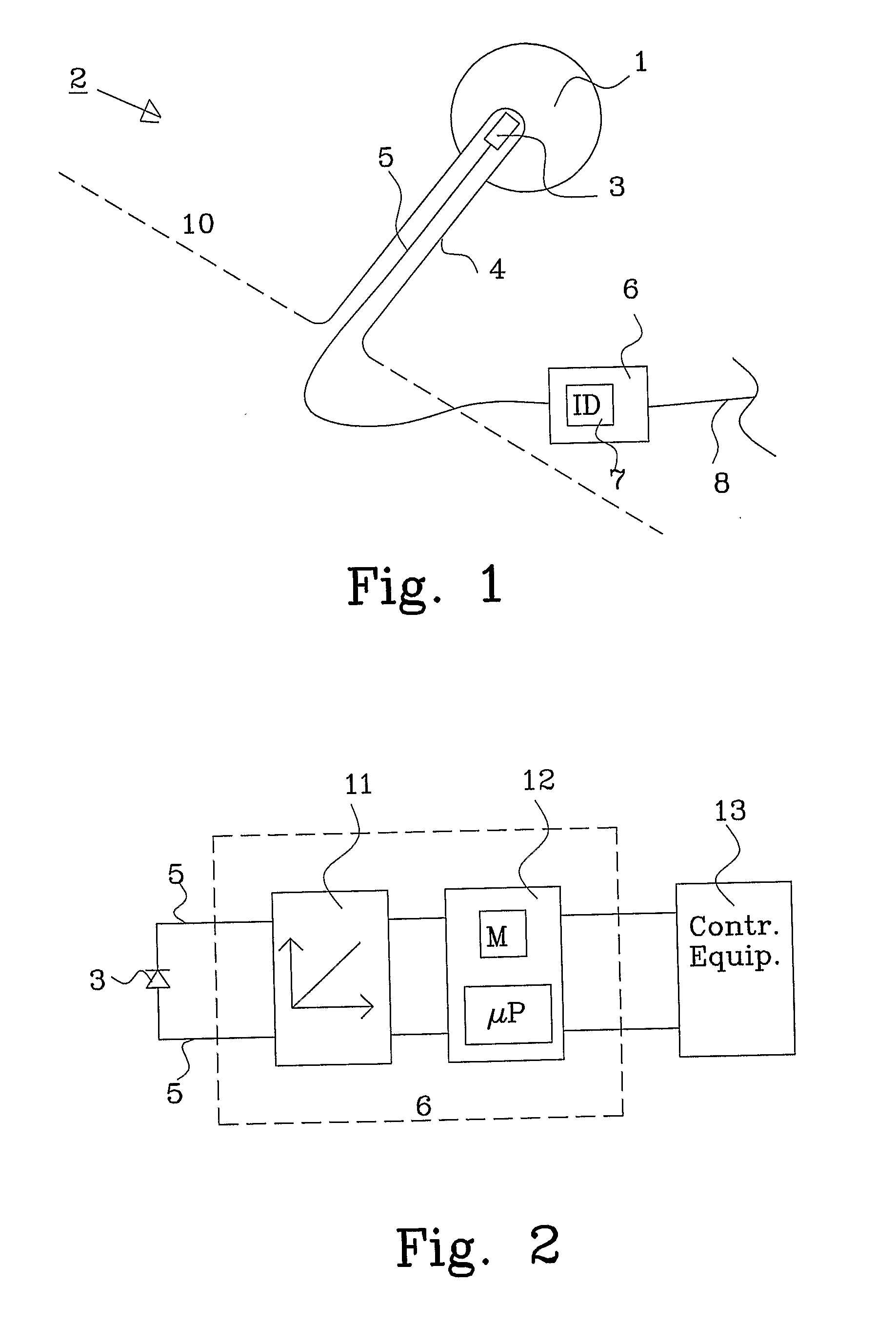
[0025]FIG. 1 shows a schematic view of a radiation monitoring device 2, in this embodiment an implant, in a living body 10 of a patient. A bio-compatible cover 4, such as a catheter, is provided either through the tissue or through a natural opening in the body. The procedure of inserting the catheter is common knowledge of a skilled person in the art, e.g. Seldinger technique.

[0026]The catheter is inserted into, or near by, a target area 1, e.g. a cancer tumor. A dose sensor 3 is inserted into the catheter 4 and is connected through wires 5 to an externally arranged dose conversion unit 6. The dose conversion unit 6 is preferably provided with an electronic ID, or a written ID-label 7 (printed or hand written), and is described in more detail in FIG. 2.

[0027]The dose conversion unit 6 converts the signal from the dose sensor to an amount of administrated dose generated by the radiation source and is preferably fastened to the outside of the patient using an adhering material, such ...

second embodiment

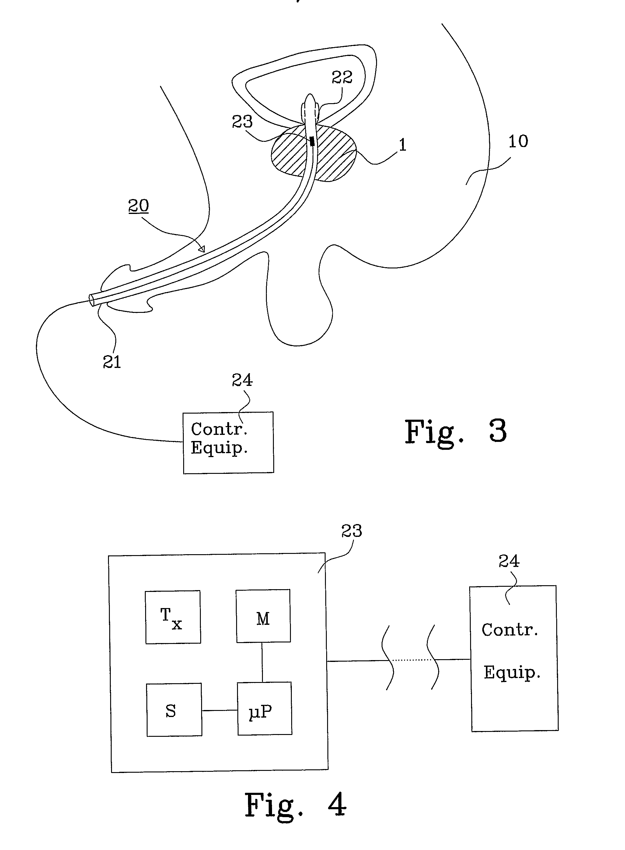
[0033]FIG. 3 shows a cross-sectional view of a radiation monitoring device 20, in this embodiment an implant, in a living body 10. The catheter 21 is in this example introduced through a natural opening and will assist in determining the administered dose when treating for instance prostate cancer. An inflatable balloon 22, which is part of the catheter 21, helps to securely position the implant relative a target area 1. A dose conversion unit 23 is arranged within the catheter 21 within the target area 1. The catheter is removed after each treatment occasion by deflating the balloon and removing the implant 20. If the catheter is provided with a through going opening, such as a lumen, the bladder may be emptied even though the catheter is maintained in position.

[0034]FIG. 4 shows a block diagram of the second embodiment of a dose conversion unit 23 in the implant of FIG. 3, and comprises in this example a transmitter Tx used for determining the position of the target area 1 (and th...

third embodiment

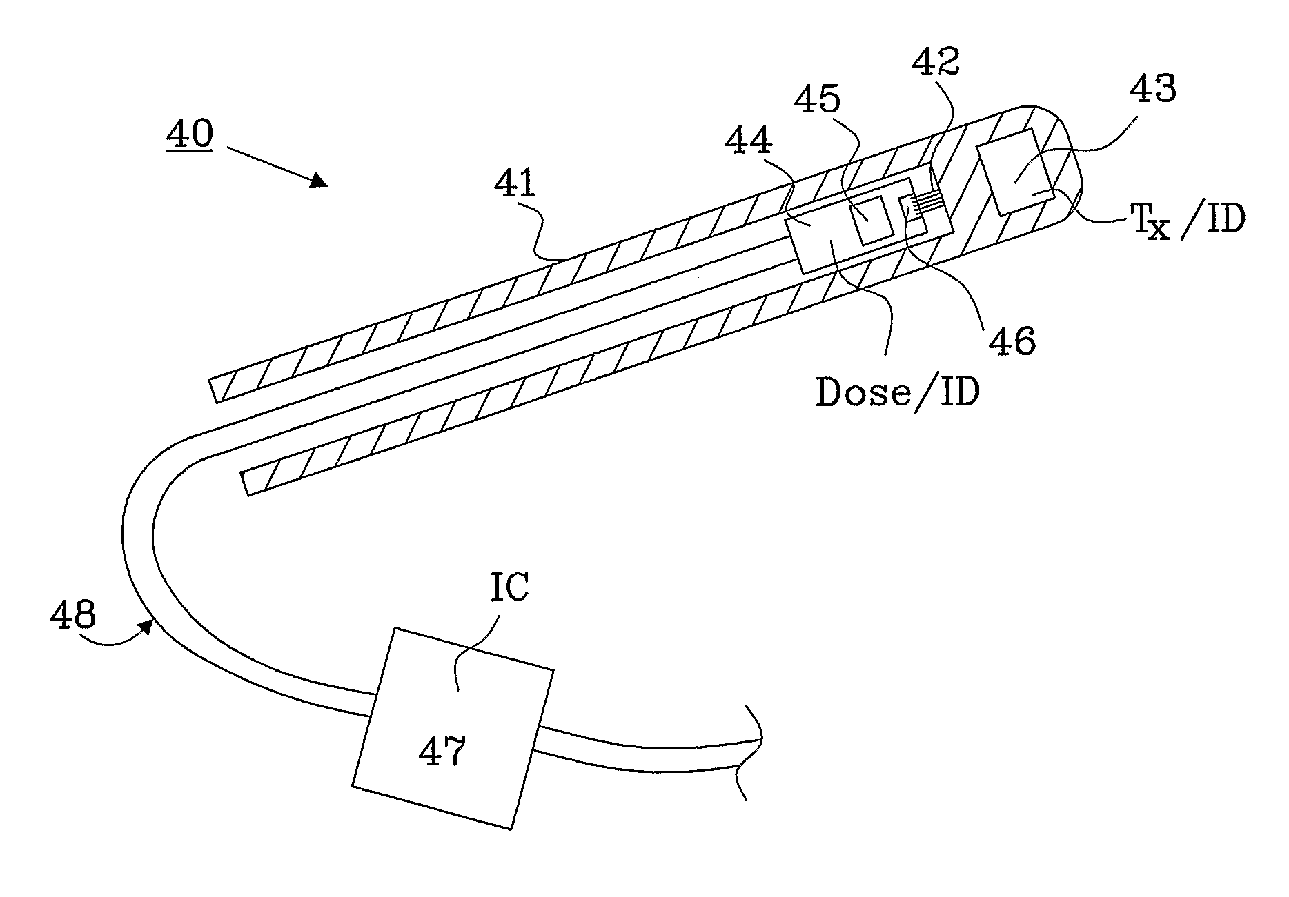
[0046]FIG. 5 shows a cross-sectional view of a radiation monitoring device 30, in this embodiment an implant, comprising a catheter 31 provided with a mechanical guide 32 and a marker 33. The marker 33 is visible when the implant is subjected to x-ray radiation. The implant further comprises a combined dose and positioning unit 34 having a transmitter Tx used to determine the position of the target area in a patient, and a dose sensor 35 used to detect the amount of administered dose in the target area.

[0047]The combined dose and positioning unit 34 is provided with a guide element 36 that is arranged to be able to mate with the mechanical guide 32 and will ensure that the unit 34 is held in the correct position during radiation treatment. The combined dose and positioning unit 34 is connected to an externally arranged integrated circuit 37 through wires 38, and may also be withdrawn from the catheter 31 between the treatment occasions. The integrated circuit 37 includes the functio...


PUM


Abstract

The present invention relates to a radiation monitoring device 2; 20; 30; 40; 50; 60; 79, such as an implant or plaster, fixable relative to a target area 1; 73; 84 within a living body 10; 74. The radiation monitoring device is provided with at least one internal element Tx; Tx / Rx; 61, 62 for tracking variations of a position of the device relative to a radiation source 76, 82 arranged outside said target area 1, 73, 84. The radiation monitoring device is further provided with a dose measuring device to detect an administrated dose from the radiation source.

Description

TECHNICAL FIELD[0001]The present invention relates to a radiation monitoring device for locating a target area and measure an administered dose, provided from a radiation source, in the target area.BACKGROUND TO THE INVENTION[0002]Today the administered dose is normally only measured on the outside of the human body during radiotherapy. Due to the lossy nature of the human body the radiation starts to disperse.[0003]There already exists a directive in Denmark with the object to ensure that it should be possible to measure the dose if an irradiation source is used. This regulation is projected to be adopted by other countries, such as France, and it could also become a standard regulation for radiation treatment.[0004]In an article with the title “An implantable radiation dosimeter for use in external beam radiation therapy”, by Charles W. Scarantino et al., published in American Association of Physicists in Medicine, September 2004, pages 2658-2670, a method for measuring administer...

Claims


Application Information

Patent Timeline
Patent Type & Authority Applications(United States)
IPC IPC(8): H05G1/38
CPCA61B19/5244A61B2019/5251A61B2019/5475A61N5/1071A61N5/1001A61N5/1048A61B2019/5483A61B2090/3983A61B2090/3975A61B34/20A61B2034/2051G01T1/161
Inventor ROSENGREN, BENGTLENNERNAS, BOIUSTIN, ROMANGUSTAFSSON, TOMAS
Owner MICROPOS MEDICAL
Why Eureka
Try Eureka