Electrophotographic toner and method for producing the electrophotographic toner

a technology of electrophotography and toner particles, applied in the field of electrophotographic toner, can solve the problems of deteriorating environmental stability, limiting the production of toner particles, and limiting the downsizing of toner particles, so as to achieve high image quality, high productivity, and cleaning stability. the effect o

Inactive Publication Date: 2008-11-27
RICOH KK
View PDF3 Cites 35 Cited by
  • Summary
  • Abstract
  • Description
  • Claims
  • Application Information

AI Technical Summary

Benefits of technology

[0012]The present invention has been made in view of the circumstances described above; that is, the present invention aims to solve the problems in the art and to attain the objects described below. It is an object of the present invention to provide an electrophotographic toner that satisfies high image quality, cleaning stability, and high productivity, and a method of producing the electrophotographic toner.

Problems solved by technology

However, the toners produced by the milling processes typically exhibit a broad particle diameter distribution and have a technical limit with respect to the downsizing of toner particles as well as a productive limit with respect to their yields.
However, the polymer dissolving-suspending processes are based on the premise that a dispersant is used in an aqueous medium, therefore, there arises such a problem that the dispersant, which typically impairs charging property of toner, remains on toner surface and deteriorate environmental stability and it has also be experienced that a considerably large amount of rinsing water is necessary to remove the remaining dispersant; as such, the processes are not necessarily satisfactory.
When using toners having a truly spherical shape and smaller particle diameters, there arises a problem in cleaning ability of the toners.
The poor cleaning ability is one of the serious problems in the toners having smaller particle diameters produced by wet processes.
In cases of spray processes for producing particles, however, as insoluble dispersing components increase the amounts in ejecting liquids, head clogging tends to occur and also production fluctuation is likely to generate due to selectivity of ejecting components, which making difficult to assure production stability and quality stability.

Method used


Image

  • Electrophotographic toner and method for producing the electrophotographic toner
  • Electrophotographic toner and method for producing the electrophotographic toner
  • Electrophotographic toner and method for producing the electrophotographic toner

Examples


first embodiment

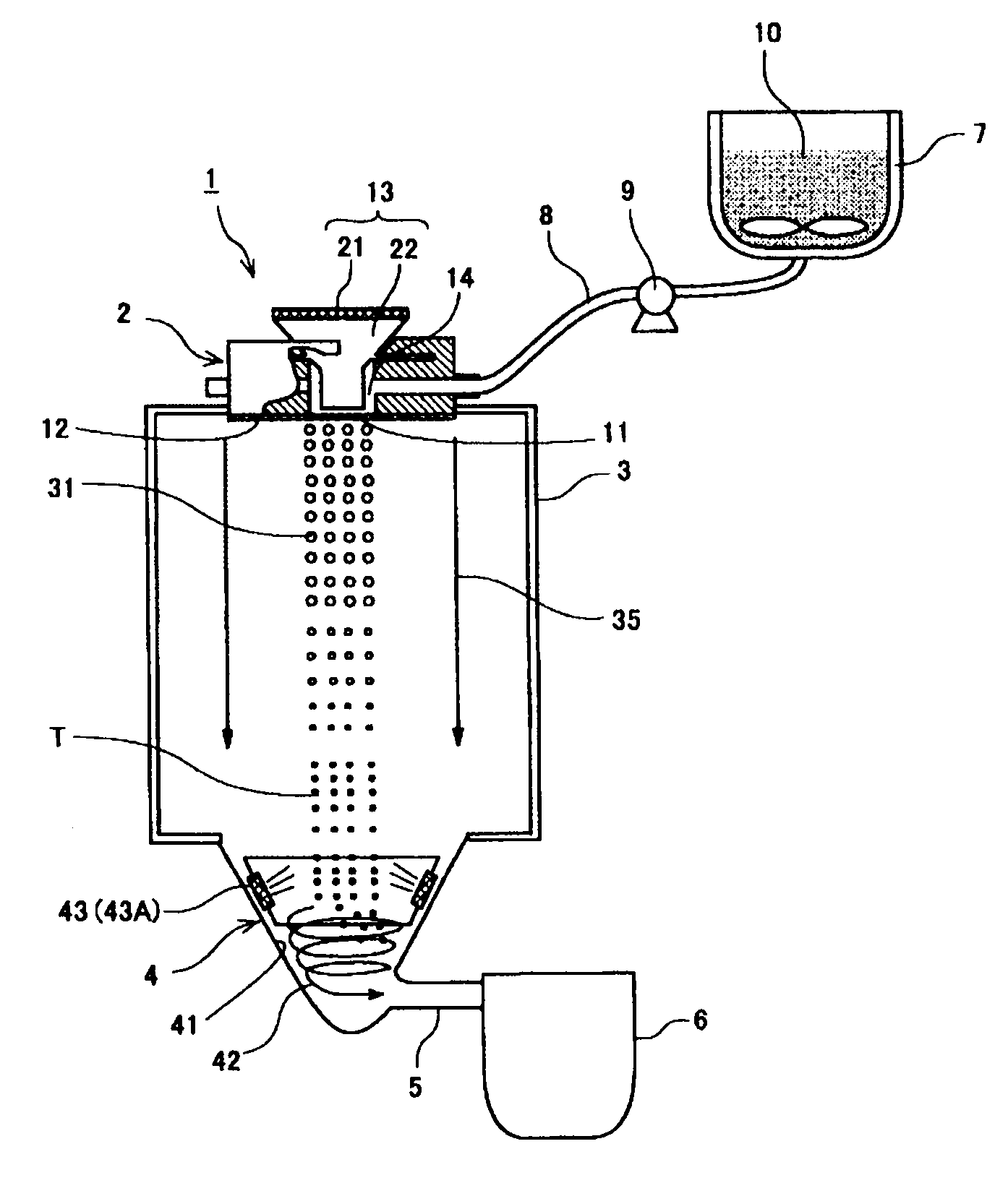
[0124]A toner production apparatus, equipped with a mechanical longitudinal vibrating device, will be explained exemplarily with reference to the schematic construction view of FIG. 1.

[0125]The toner production apparatus 1 is equipped with a droplet ejection unit 2 to eject the toner ingredient-containing liquid that contains at least the resin and the colorant, a particle forming portion 3 in which droplets of the toner ingredient-containing liquid ejected from the droplet ejection unit 2 are solidified to form toner particles T (drying / solidifying unit, drying / solidifying) and the droplet ejection unit 2 is disposed above the particle forming portion 3, a toner collecting portion 4 to collect the toner particles T formed at the particle forming portion 3, a toner storage portion 6 to store the toner particles T that are collected at the toner collecting portion 4 and conveyed through a tube 5, a raw material containing portion 7 to contain the toner ingredient-containing liquid 10...

second embodiment

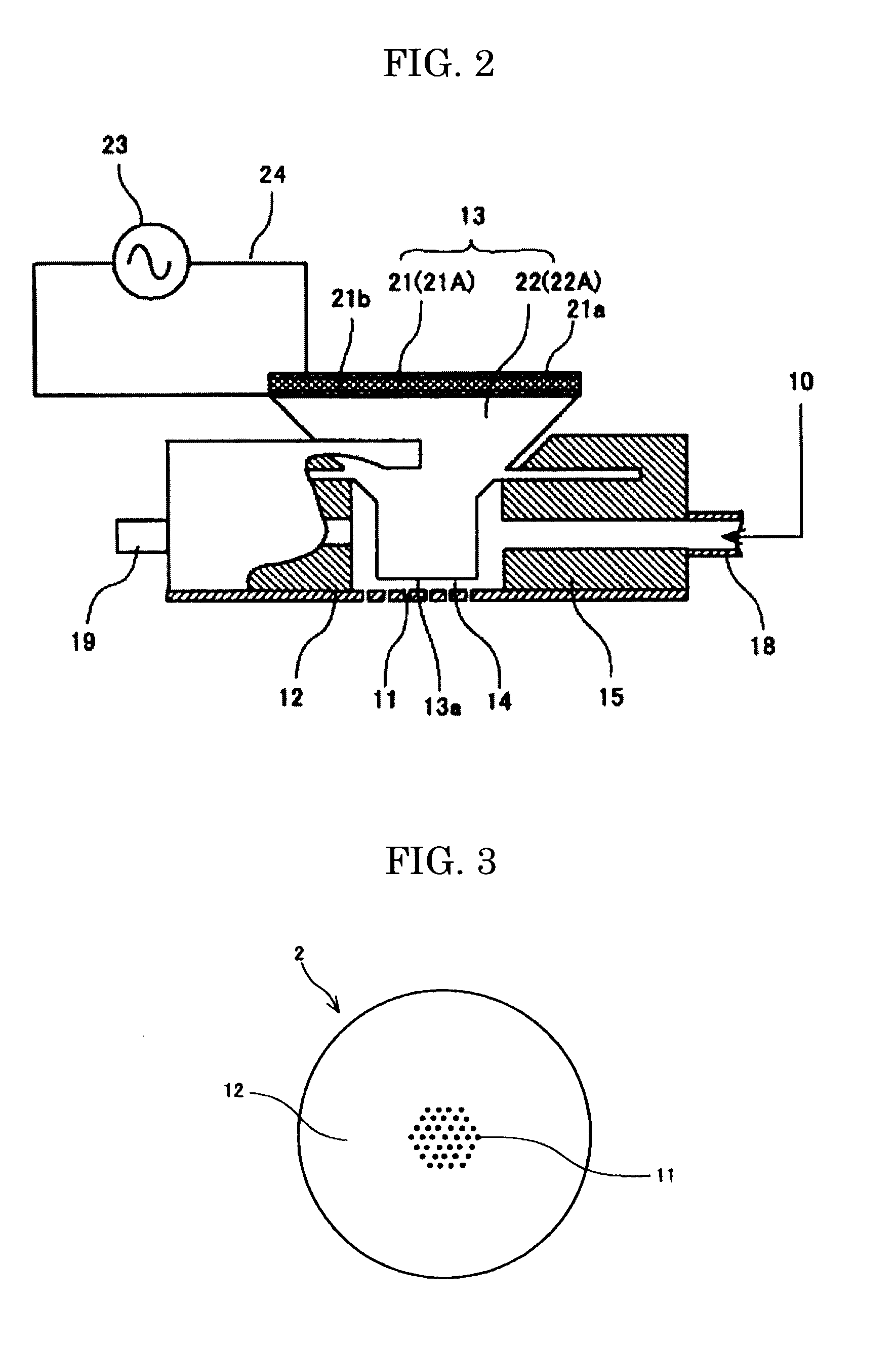
[0147]FIG. 11 shows a toner production apparatus similar as that of FIG. 1 except that the droplet ejection unit is exchanged into a ring type.

[0148]The droplet ejection unit 2 of ring type will be explained with reference to FIGS. 12 to 14. FIG. 12 is a cross-sectional view that illustrates the droplet ejection unit 2; FIG. 13 is a view schematically showing the bottom portion of the droplet ejection unit 2 that corresponds to FIG. 12 viewed from downside; and FIG. 14 is a schematic cross-sectional view that illustrates the droplet forming device.

[0149]The droplet ejection unit 2 is equipped with the droplet forming device 11 that makes the toner ingredient-containing liquid 10, containing at least the resin and the colorant, into droplets and ejects them and the flow path member 15 to which a reservoir 14 (liquid flow path) is formed for supplying the toner ingredient-containing liquid 10 into the droplet forming device 11.

[0150]The droplet forming device 16 is constructed from th...

third embodiment

[0168]The third embodiment of the inventive method for producing electrophotographic toner, which being different from the periodic droplet forming methods described above, is a method to produce a toner with a uniform particle diameter distribution, in which a solution or a dispersion is fed to a reservoir in a constant rate, the raw material liquid is ejected to a particle forming space from plural through pores at the reservoir while vibrating the reservoir by a vibrating device that contact with a part of the reservoir, thereby the raw material liquid is made into droplets through from a column-like shape to a constricted condition.

[0169]FIG. 22 is a schematic constitutional view of an apparatus to produce an electrophotographic toner that explains the third embodiment of the inventive method for producing an electrophotographic toner.

[0170]The reservoir is preferably made of metal members such as stainless steel and aluminum and has a pressure tightness of about 10 MPa in order...


PUM

PropertyMeasurementUnit
volume average particle diameteraaaaaaaaaa

Abstract

Provided are an electrophotographic toner and a method for producing the electrophotographic toner that satisfy high image quality, cleaning stability, and high productivity.
The electrophotographic toner is produced by spray-drying a toner ingredient-containing liquid, wherein the toner ingredient-containing liquid dissolves or disperses at least a resin, a low molecular mass organic material, and a colorant in an organic solvent, the resin is soluble in the organic solvent, the low molecular mass organic material is a crystalline compound or a composition of crystalline compounds that is soluble in the organic solvent, the toner ingredient-containing liquid contains substantially no particles having a particle diameter of 500 nm or more, the crystalline compound or the composition of crystalline compounds crystallizes upon spray-drying to deform toner particles into a circularity of 0.93 or higher to 0.98 or less, and volume average particle diameter of the toner particles is 3.0 μm or higher to less than 7.0 μm.

Description

BACKGROUND OF THE INVENTION[0001]1. Field of the Invention[0002]The present invention relates to an electrophotographic toner used for electrophotography, more specifically to an electrophotographic toner that is produced by spray processes, has relatively small particle diameters, and exhibits stable productivity and favorable cleaning ability, and also a method for producing the toner.[0003]2. Description of the Related Art[0004]Higher image quality has been demanded in the fields of copiers, printers, etc. of electrophotographic systems in recent years, and downsizing of toner particles has been vigorously investigated in order to satisfy the demand.[0005]Conventionally, toners have been produced by milling processes in a way that a binder resin, a colorant, etc. are melted and kneaded and the kneaded product is milled and classified. However, the toners produced by the milling processes typically exhibit a broad particle diameter distribution and have a technical limit with resp...

Claims


Application Information

Patent Timeline
Patent Type & Authority Applications(United States)
IPC IPC(8): G03G9/125
CPCG03G9/0804G03G9/0806G03G9/0819G03G9/0827G03G9/08711G03G9/08755G03G9/08795G03G9/08797G03G9/09716G03G9/09725
Inventor SUZUKI, KAZUMIWATANABE, YOHICHIROHHONDA, TAKAHIRONORIKANE, YOSHIHIROOHTANI, SHINJISUGIMOTO, TSUYOSHI
Owner RICOH KK
Why Eureka
Try Eureka